
Inside the Rotary Table: A Step-by-Step Engineering Explanation of Injection Blow Molding Machine Operation
The three-station rotary injection blow molding machine — commonly called an IBM machine — is one of the most elegantly engineered platforms in plastic container manufacturing. In a single compact frame, it injects plastic around a steel core pin, inflates the still-hot parison into a finished bottle, and ejects the completed container, all within a cycle measured in seconds and all happening simultaneously at three stations at once.
Yet for all its output efficiency and dimensional precision, the IBM machine is often poorly understood by buyers evaluating it for the first time — or even by production engineers who operate it daily without fully understanding what is happening mechanically at each station and why each engineering parameter matters. This guide explains exactly how a three-station rotary IBM machine works: the mechanical architecture, the function of each station, the role of each key subsystem, and the engineering principles that determine why IBM produces flash-free, precise containers faster and more cleanly than any comparable single-step blow molding alternative.
1. Machine Architecture Overview
A three-station rotary IBM machine is built around one central mechanical concept: a horizontal rotary table that carries a set of precision steel core pins in a triangular arrangement, indexing 120 degrees at a time through three fixed processing stations.
Every component of the machine — the injection unit, the clamping system, the blow assembly, the hydraulic or servo drive system, and the PLC control cabinet — is arranged around this central rotary table. The table does not move continuously; it lifts, indexes 120 degrees, lowers, and dwells while all three stations work simultaneously. Then the sequence repeats.
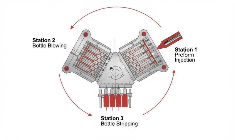
The six major assemblies of a three-station rotary IBM machine are:
(1) Injection Plasticising Unit
Reciprocating screw, barrel, hopper, and nozzle — converts solid resin granules into controlled melt and delivers it to the injection cavity.
(2) Clamping System
Hydraulic or servo actuators that open and close the injection and blow cavity blocks against the rotary table platens, generating the clamping force that keeps cavities sealed during injection and blowing.
(3) Rotary Table and Core Pins
The precision-machined rotating platen carrying hardened steel core pins — the physical link between all three stations and the element that transfers the parison from injection through blowing to stripping without intermediate handling.
(4) Blow Assembly
Blow cavity block, blow clamping actuator, and compressed air circuit — encloses the parison and inflates it to its final container shape at Station 2.
(5) Hydraulic / Servo Power Unit
The drive system for all mechanical movements — clamping, injection, table lift and rotation, stripping. On hydraulic IBM machines, this is a hydraulic pump and valve bank. On all-electric machines, it is a set of independent servo motors.
(6) PLC Control Cabinet
Industrial PLC and HMI touchscreen that coordinates all machine movements, monitors all process parameters, stores production recipes, and displays fault diagnostics.
2. The Rotary Table — Heart of the IBM Machine
The rotary table is the defining mechanical feature of the three-station IBM machine. It is a precision-machined ductile cast iron or steel platen, typically 600 to 1,300 mm in length depending on the machine model, mounted on a central vertical shaft. The table carries the core pin assemblies — three sets of one or more hardened steel core pins arranged at 120-degree intervals around the table perimeter.
The table operates in a repeating four-step motion sequence within every production cycle:
1
LIFT
Table rises hydraulically (70 mm stroke) to disengage core pins from all three station cavity blocks simultaneously
2
INDEX
Table rotates 120 degrees, advancing each core pin set to the next station in sequence
3
LOWER
Table descends to re-engage core pins with the cavity blocks at their new stations, bringing parisons into register
4
DWELL
All three stations operate simultaneously while the table is stationary — injection, blowing, and stripping all occur in parallel
The precision of the rotary table indexing is critical to product quality. Core pins must re-register with injection and blow cavities to within typically plus or minus 0.05 mm on every cycle — day after day, at millions of cycles. This is why IBM rotary table guide columns are ground to H6/g5 tolerance fits with hardened running surfaces, and why table lift height (typically 70 mm across all ZQ-series machines) is precisely controlled rather than simply mechanical stop-limited.
Engineering note: The 70 mm table lift stroke used across our entire ZQ-series (ZQ40 through ZQ135) is not arbitrary — it is the minimum clearance required to fully disengage the tallest core pin from the deepest injection cavity while providing sufficient rotational clearance for the table to index without interference between the core pins and the fixed cavity blocks.
3. Station 1: Injection — How the Parison Is Formed
Station 1 is where the process begins. When the rotary table has indexed and lowered, the core pin set at Station 1 is positioned precisely within the injection cavity block. The clamping system closes the injection cavity halves against the core pins with the full machine injection clamping force — 400 KN on a ZQ40 up to 1,350 KN on a ZQ135. This clamping force must exceed the injection pressure force across the projected cavity area to prevent any leakage of melt from the parting line.
What happens at Station 1, step by step:
Cavity Clamping
The injection cavity block closes around the core pins. The cavity defines the external shape of the parison body and — critically — the precise internal profile of the bottle neck thread. The clamping force seals the parting line against injection pressure, which typically reaches 80 to 150 MPa in the cavity.
Melt Injection
The injection unit screw advances, driving molten resin through the nozzle and into the injection cavity via the sprue and runner system. Melt fills the annular space between the core pin outer surface and the cavity inner surface, forming the parison wall. On machines with multiple cavities, the runner system must be balanced to fill all cavities simultaneously.
Packing and Hold Pressure
After fill, the screw maintains hold pressure for a defined dwell time (typically 1 to 4 seconds). This compensates for volumetric shrinkage of the melt as it cools, ensuring the parison fully replicates the cavity surface. Insufficient hold pressure produces sink marks and dimensional undersize; excessive hold pressure produces internal stress and gate vestige.
Screw Recovery (Plasticising)
While the parison cools on the core pin under hold pressure, the screw begins rotating to plasticise the next shot. Rotation melts and homogenises incoming resin granules, pushing melt forward while the screw retracts against back pressure. Shot size is determined by screw stroke — the distance the screw retracts during recovery.
Cavity Opening and Table Lift
Once the parison has cooled to the optimal blowing temperature (hot enough to be inflatable, cool enough to hold shape — typically 10 to 40 degrees above the resin’s softening point), the injection clamping system opens the cavity halves. The parison remains on the core pin. The rotary table then lifts and indexes to advance the parison-bearing core pin to Station 2.
Why IBM neck threads are superior to EBM: The neck thread is formed in the injection cavity at Step A, to injection moulding tolerances of plus or minus 0.1 mm or better. In extrusion blow molding, the neck is formed from a pinch-off of an extruded tube — dimensional accuracy is limited to plus or minus 0.3 to 0.5 mm and flash trimming is required. IBM neck precision is why pharmaceutical, cosmetic, and agrochemical packaging — all requiring certified, leak-proof thread engagement with precision caps and fitments — is dominated by IBM technology.
4. Station 2: Blowing — How the Container Is Formed
At Station 2, the parison — still on its core pin and still at blowing temperature — is enclosed within the blow cavity block. This is where the flat-walled parison becomes the final three-dimensional container shape.
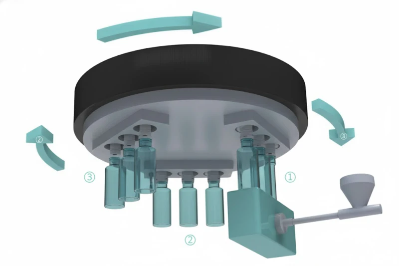
What happens at Station 2, step by step:
Blow Cavity Clamping
The blow cavity block closes around the parison with the blow clamping force (60 KN on ZQ40 up to 200 KN on ZQ135). The blow cavity defines the final external shape of the container body — diameter, height, embossing, label panels, and any body detail. The blow clamping force must be sufficient to prevent the blow parting line from separating under inflation pressure.
Air Inflation
Compressed air at 0.7 to 1.2 MPa is introduced through the hollow centre of the core pin. The air pushes the parison wall outward in all radial directions simultaneously, expanding it against the blow cavity walls. The parison material thins as it expands — the wall thickness of the final container is determined by the parison wall thickness and the blow ratio (cavity diameter divided by parison outer diameter).
Cooling Under Pressure
Once fully inflated against the cavity walls, the container is held under air pressure while the cooling water channels within the blow cavity walls extract heat from the container through conduction. Cooling time depends on container wall thickness, resin thermal properties, and cavity cooling water temperature. Typically, a dedicated chiller maintains water temperature at 10 to 15 degrees C for optimal cycle time.
Air Exhaust and Blow Cavity Opening
After sufficient cooling, the blow air pressure is exhausted through the core pin air channel. The blow cavity block opens, leaving the completed container on the core pin. The core pin now carries a finished container ready for ejection at Station 3. The rotary table lifts and indexes to advance the container-bearing core pin to Station 3.
Why retained heat matters: The parison arrives at Station 2 still at blowing temperature from the injection step — no reheating is required. This is a fundamental advantage of one-step IBM over two-step processes (where preforms are cooled to ambient and must be reheated before blowing). Eliminating the reheating step saves energy, shortens cycle time, and avoids the crystallinity and optical issues that reheating can introduce in PET.
5. Station 3: Stripping — Container Ejection
Station 3 is mechanically the simplest of the three stations but operationally critical. If stripping fails — a container sticks to the core pin, or the stripper mechanism jams — the production line stops. The stripping mechanism must reliably eject every container from every core pin at full cycle speed, cycle after cycle, across millions of production hours.
At Station 3, the core pin set carries the finished, cooled container. A stripper plate or mechanical ejector ring engages the container neck — which is the most rigid part of the container after injection moulding — and pushes the container downward off the core pin while the core pin is held stationary. The container falls or is guided onto a take-off conveyor or collection system below.
The stripping stroke on IBM machines ranges from 220 mm on smaller models (ZQ40, ZQ60) to 280 mm on the largest (ZQ135). The stroke must be long enough to fully disengage the container from the core pin before the next table index. On high-cavity-count tooling where the core pin array is deep, the longer stripping stroke of larger machines is essential for reliable ejection.
Engineering detail — why stripping force matters: The container must be stripped from the core pin against the friction of the resin on the core pin surface — which is increased by the thermal shrinkage of the container wall as it cools (the container grips the pin more tightly as it shrinks). Core pin surface finish, draft angle, and material selection all affect stripping force. DLC-coated core pins have lower friction than uncoated steel, reducing required stripping force and enabling faster ejection at higher cycle rates.
After stripping, the now-empty core pins at Station 3 remain stationary while the rotary table indexes, advancing them back to Station 1 for the next injection cycle. The entire rotary table — three sets of core pins at three stages of production — completes one full revolution for every three production cycles, bringing every core pin set back to Station 1 every three indexing movements.
6. Why All Three Stations Run Simultaneously — and Why It Matters
The most important productivity principle of the three-station IBM machine is that injection, blowing, and stripping all happen at the same time. While one set of core pins is being injected at Station 1, the previous set is being blown at Station 2, and the set before that is being stripped at Station 3.
This means that from the machine’s total cycle time perspective, you pay the time cost of only one station operation per cycle — not three in sequence. Consider what the cycle time would be if stations ran sequentially: 3 seconds injection + 2 seconds blowing + 1 second stripping = 6 seconds per cycle. With simultaneous three-station operation, the total cycle time is determined by the longest single station operation — typically the injection/cooling phase at approximately 3.5 to 4 seconds for hydraulic machines, or 2.5 seconds for all-electric machines.
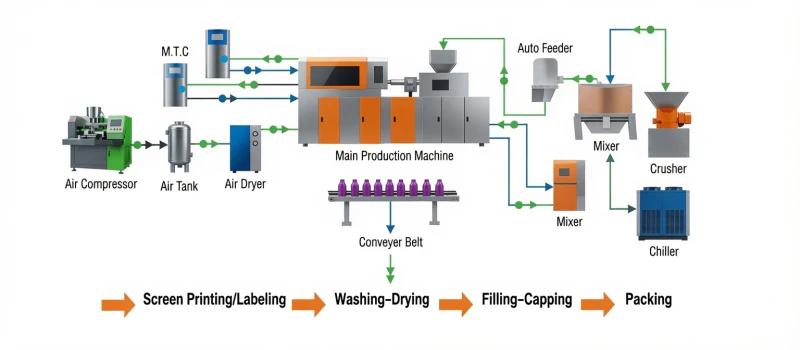
The practical output consequence of simultaneous three-station operation is significant. Consider a 4-cavity IBM machine producing 30 ml pharmaceutical vials at 8-second total cycle time (including cooling):
Output Calculation Example — 4-Cavity IBM Machine, 30 ml Vial
4
cavities per shot
8 s
total cycle time
450
cycles per hour
1,800
bottles per hour
43,200
bottles per 24 hours
On our all-electric ZQ60HE at 2.5-second dry cycle and optimised total cycle, output for 30 ml pharmaceutical vials reaches up to 115,000 bottles per 24 hours — a rate only achievable because of the simultaneous three-station architecture that means machine dwell time is never wasted on sequential station sequencing.
7. Key Subsystems: Injection Unit, Hydraulics, and PLC Control
The Injection Plasticising Unit
The injection unit converts solid resin granules into a metered, homogeneous melt and delivers it to the injection cavity. The key components are the reciprocating single screw (diameter 40 mm to 70 mm depending on machine model), the heated barrel (3+N to 6+N independently controlled temperature zones), the non-return valve at the screw tip (prevents melt from flowing back during injection), and the nozzle (the interface between the barrel and the injection cavity sprue). Screw L/D ratio of 22:1 across the ZQ series provides the residence time and shear energy needed for complete, uniform plastication across PET, PP, HDPE, LDPE, PETG, and PVC resins.
The Hydraulic or Servo Drive System
Conventional hydraulic IBM machines use a servo-pump hydraulic power unit to drive all machine movements — injection, clamping, table lift, table rotation, and stripping — through a proportional valve manifold. System pressure is typically 14 MPa. The ZQ80, ZQ110, and ZQ135 use dual independent servo-pump circuits to prevent hydraulic pressure competition between injection and clamping movements at high tonnage. All-electric IBM machines (ZQ60HE) replace every hydraulic circuit with independent servo motors — one per motion axis — eliminating hydraulic oil entirely and reducing operating power consumption from 52 to 70 percent of installed power (hydraulic) to 15 to 25 percent (all-electric).
The PLC Control System
Siemens or Mitsubishi PLC with a colour industrial HMI touchscreen coordinates all machine movements with millisecond-level timing precision. The PLC manages injection velocity and pressure profiling (often 5 to 10 programmable injection stages per cycle), barrel zone temperature closed-loop control, clamping force timing, table indexing sequences, blow air pressure and timing, cooling water control, and alarm/fault management. All parameters are stored as named production recipes — enabling rapid product changeover without manual parameter re-entry. The all-electric ZQ60HE adds individual servo axis monitoring (current, velocity, position) and Modbus TCP / Ethernet IP connectivity for MES integration and remote diagnostics.
8. The Complete IBM Machine Cycle — Step-by-Step Timeline
The following timeline shows a complete IBM machine cycle for a hydraulic machine at approximately 4-second dry cycle, with a typical total cycle time of 10 to 14 seconds (including cooling) for a medium-size PP container. All events at Stations 1, 2, and 3 are simultaneous unless noted:
| Time (s) | Station 1 (Injection) | Station 2 (Blow) | Station 3 (Strip) |
|---|---|---|---|
| 0.0 to 0.5 | Injection cavity closes and clamps | Blow cavity closes and clamps | Stripper engages container neck |
| 0.5 to 2.5 | Melt injection — fill and pack | Air inflation at 0.7 to 1.2 MPa | Container pushed off core pin (220 to 280 mm stroke) |
| 2.5 to 3.0 | Hold pressure dwell | Container cooling under air pressure | Stripper retracts; empty core pins wait |
| 3.0 to 8.0 | Cooling on core pin; screw recovery (plasticising next shot) | Container continues cooling | Station idle — core pins at ambient, ready for Station 1 |
| 8.0 to 8.5 | Injection cavity opens | Blow air exhausts; blow cavity opens | — |
| 8.5 to 9.0 | TABLE LIFT — all cavities simultaneously open and clear | ||
| 9.0 to 9.5 | TABLE INDEX 120 degrees — all core pin sets advance to next station | ||
| 9.5 to 10.0 | TABLE LOWER — core pins re-engage with new station cavity blocks | ||
| 10.0 — | NEW CYCLE BEGINS simultaneously at all three stations | ||
Note: Timeline is illustrative for a medium PP container at approx. 10-second total cycle. Actual timing varies by container size, resin, wall thickness, and cooling conditions. All-electric IBM (ZQ60HE) achieves 2.5-second dry cycle (Steps 0 to 4) and proportionally shorter total cycles.
9. Hydraulic vs All-Electric IBM: What Changes in the Machine Architecture

The three-station rotary process is identical in hydraulic and all-electric IBM machines. What changes is the mechanism driving each movement:
| Machine Motion | Hydraulic IBM | All-Electric IBM (ZQ60HE) |
|---|---|---|
| Injection (screw forward) | Hydraulic injection cylinder | 22 KW injection servo motor |
| Screw rotation (plasticising) | Hydraulic screw drive motor | 18 KW feeding servo motor |
| Injection clamping | Hydraulic clamp cylinders | 15 KW clamping servo motor |
| Blow clamping | Hydraulic blow clamp cylinder | 15 KW clamping servo motor |
| Table lift and lower | Hydraulic lift cylinder | Carriage servo motor (1 KW) |
| Table rotation (120 deg index) | Hydraulic rotary actuator | 2.9 KW rotary servo motor |
| Stripping | Hydraulic stripper cylinder | 0.4 KW ejector servo motor |
| Hydraulic oil | Required — 150 to 400 L reservoir | None — zero oil in machine |
| Dry cycle time | 3.5 to 4 seconds | 2.5 seconds |
| Operating power | 52 to 70 percent of installed | 15 to 25 percent of installed |
10. The IBM Mould: Core Pins, Cavities, and Tooling
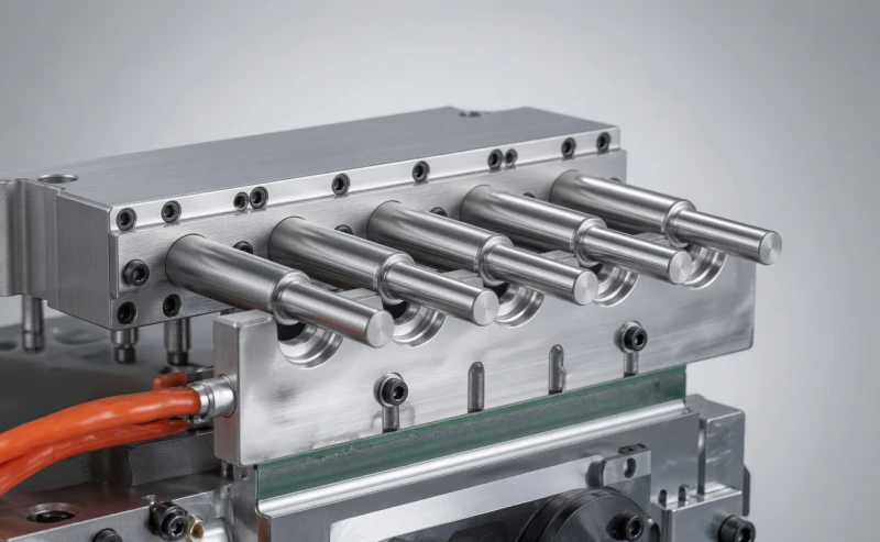
The IBM mould is not a single tool — it is a matched set of three precision-engineered components that together define the container produced:
Core Pins
The core pin is the most critical component in the IBM mould. It defines the container’s internal dimensions, carries the parison from injection through blowing to stripping, and conveys blow air through its hollow centre. Core pins are precision-ground from H13 hot-work tool steel and coated with DLC (Diamond-Like Carbon) or hard-chrome for reduced friction and extended service life. The core pin outer surface defines the container’s internal diameter and must maintain dimensional accuracy within plus or minus 0.01 mm after millions of thermal cycles.
Injection Cavity Block
The injection cavity defines the parison’s external shape and — most importantly — the bottle neck thread in full injection moulding accuracy. Injection cavities are machined from P20 or H13 tool steel, hardened to 50 to 54 HRC, and finished to a mirror polish for optical-quality container surfaces. Cooling channels are drilled within the cavity block to extract heat uniformly from the parison during hold pressure and cooling. Runner and gate geometry is engineered to fill all cavities simultaneously in balanced multi-cavity configurations.
Blow Cavity Block
The blow cavity defines the container body’s final external shape, dimensions, surface texture, and any embossing or label panel geometry. Split into two halves that close around the parison at Station 2, the blow cavity is typically machined from beryllium copper or aluminium alloy for rapid heat extraction, or from P20/H13 steel for higher-volume production requiring greater wear resistance. Cooling channels must be positioned to extract heat uniformly from the container body wall during the blow cooling phase.
The service life of IBM mould tooling is substantially longer than equivalent EBM tooling because IBM moulds experience no flash pinch-off impact on every cycle. Well-maintained H13 core pins with DLC coating typically achieve 3 to 5 million production cycles before reconditioning — and often considerably more on smaller, lighter-parison containers. The injection and blow cavity blocks typically outlast the core pins by a factor of 2 to 3.
11. Key Process Parameters and Their Effect on Container Quality
Understanding the key IBM process parameters and how they affect container quality is essential for both machine buyers evaluating process capability and production engineers setting up new container formats.
| Parameter | Effect on Container Quality | Too Low / Too High |
|---|---|---|
| Barrel Zone Temperatures | Controls melt viscosity and homogeneity. Each zone independently controlled for optimal plastication profile from feed to nozzle. | Too low: incomplete melt, splay. Too high: degradation, discolouration, reduced molecular weight. |
| Injection Pressure | Drives melt into the injection cavity. Must be sufficient to fill all cavities completely before gate freeze-off. | Too low: short shots. Too high: flash at parting line if below clamping force capacity. |
| Hold Pressure and Time | Compensates for thermal shrinkage during cooling. Determines parison dimensional accuracy and weight consistency. | Too low: sink marks, underweight. Too high: internal stress, difficult stripping, gate vestige. |
| Injection Clamping Force | Seals injection cavity parting line against injection pressure. Must exceed cavity pressure times projected area. | Too low: flash on injection parting line. (Too high has no quality effect but wastes energy.) |
| Parison Temperature at Blowing | Must be within the resin’s blowing window — above softening point but below flow temperature. Determines blow quality and wall uniformity. | Too cold: incomplete blow, wall tearing. Too hot: sagging parison, thin bottom, loss of neck dimensions. |
| Blow Air Pressure | Drives parison against blow cavity walls. Must be sufficient to fully form the container against cooling cavity walls. | Too low: incomplete formation, rounded corners. Too high: risk of blow cavity flash if blow clamp is marginal. |
| Blow Cooling Time | Time the container spends in the blow cavity cooling to ejectable temperature. Primary determinant of total cycle time on thick-wall containers. | Too short: hot container deforms on stripping. Too long: unnecessarily extends cycle time and reduces output. |
| Cooling Water Temperature | Lower chilled water temperature increases heat extraction rate from blow cavity, directly reducing cooling time and total cycle. | Too warm: slow cooling, long cycle. Too cold: condensation risk on cavity surfaces may affect container surface quality. |
| Screw Back Pressure | Resistance applied during screw recovery — controls melt density, homogeneity, and degassing during plasticising. | Too low: poor melt homogeneity, air bubbles. Too high: extended recovery time, excessive shear heat. |
12. Frequently Asked Questions
Q: Why do IBM machines use three stations rather than two or four?
Three stations represent the minimum number that allows complete separation of the injection, blowing, and stripping operations while maintaining simultaneous parallel operation. Two stations would require either injection and blowing to share one station (impossible to do simultaneously) or stripping to be incorporated into the blow station (which would limit cycle time). Four stations are used by ISBM machines to insert a conditioning station between injection and blowing — this is necessary for ISBM’s bi-axial stretch orientation but not needed in IBM where no stretch orientation is required.
Q: What limits the minimum dry cycle time on a hydraulic IBM machine?
The minimum dry cycle on hydraulic IBM machines is limited by the hydraulic system’s response time — specifically, the time required for hydraulic pressure to build to full clamping force after a proportional valve opens, the time for the hydraulic rotary actuator to complete a 120-degree table index, and the time for hydraulic actuators to complete the table lift and lower strokes. Proportional valve response, oil viscosity (temperature-dependent), and hydraulic pump flow rate all contribute. This is why the ZQ60HE all-electric machine achieves a 2.5-second dry cycle — servo motors respond to position commands in milliseconds without the hydraulic lag time that limits conventional machines to 3.5 to 4 seconds.
Q: How many cavities can an IBM machine run simultaneously?
Cavity count per IBM machine is limited by the platen size and the total shot weight across all cavities. On our ZQ40 (480×340 mm platen, 260 g max shot), a typical 30 ml vial mould runs 4 to 6 cavities. On the ZQ135 (1,300×500 mm platen, 650 g max shot), up to 16 to 20 cavities are achievable for small containers. The specific cavity count for your container is determined by our mould design team based on container dimensions, shot weight, and platen geometry — we provide a free cavity layout drawing with every machine project inquiry.
Q: Can an IBM machine change between container sizes without a full mould changeover?
No. Each container size requires matched injection cavity, core pin, and blow cavity tooling. Changing container size requires a physical mould changeover — removing the existing injection cavity block, core pins, and blow cavity, and fitting the new matched tooling set. However, the PLC recipe system allows all process parameters for the new container to be recalled instantly from memory, so only the physical tooling change time adds to the product changeover duration. Well-organised IBM operations can complete a mould changeover in 2 to 4 hours, depending on cavity count and container size.
Q: What is the service life of IBM machine core pins?
High-quality H13 tool steel core pins with DLC or hard-chrome coating typically achieve 3 to 5 million production cycles before reconditioning is required. At 4-second cycles running 20 hours per day, this represents approximately 4 to 7 years of production before the first reconditioning — and reconditioned core pins can often be returned to service for comparable additional service life. Smaller, lighter parisons (under 50 ml) are gentler on core pins than large-parison containers, so service life is often longer at the small end of the container range. Core pin inspection should be included in quarterly maintenance routines to catch dimensional drift before it affects container quality.
13. Conclusion
The three-station rotary IBM machine is an engineering achievement that delivers remarkable output efficiency from a compact, integrated platform — because every element of its architecture, from the rotary table indexing sequence to the simultaneous three-station operation, is optimised around a single principle: eliminate idle time and keep all tooling productive at every moment of every cycle.
Understanding how the machine works — why the rotary table uses a lift-index-lower sequence, why the injection cavity clamping force must exceed cavity pressure, why retained parison heat eliminates reheating, and why simultaneous three-station operation determines cycle time — is what separates buyers who specify the right machine for their application from those who choose based on price alone and discover the mismatch in production.
Whether you are evaluating your first IBM machine or adding capacity to an existing line, our engineering team is available to discuss your specific container, resin, and production volume requirements — and to recommend the right machine model, cavity configuration, and mould design for your application.
Talk to an IBM Machine Engineer — Free
Share your container drawing and production volume target. Our team will recommend the right IBM machine model, estimate cavity count and output, and provide a factory-direct quote — within 24 hours, no obligation.