
The Sequence Between Machine Delivery and Consistent Production Is Not Guesswork — It Is a Defined Engineering Programme Whose Correct Execution Determines Whether Commissioning Takes Two Weeks or Two Months
Every IBM machine installation follows a predictable commissioning sequence: site preparation and machine installation, utilities connection and verification, machine functional testing without mould, mould installation and alignment, initial process parameter development, first article inspection against the container specification, process window characterisation, and — for pharmaceutical and food applications — formal IQ/OQ/PQ validation. The total elapsed time from machine delivery to sustained production output varies from two weeks for an experienced team with a well-prepared site to three months or more for a team encountering each step for the first time without a defined protocol.
The difference between these two outcomes is almost entirely the quality of preparation and the discipline of the commissioning sequence. This guide provides the complete commissioning protocol for IBM machines — from pre-delivery site preparation through to production readiness sign-off. It covers the engineering requirements at each stage, the checks that must be completed before advancing to the next stage, and the specific IBM machine considerations that differ from general injection moulding commissioning. It is written for production engineers, plant managers, and quality teams who are responsible for bringing a new IBM machine or a new IBM container project into production.
1. Pre-Delivery Site Preparation: What Must Be Ready Before the Machine Arrives
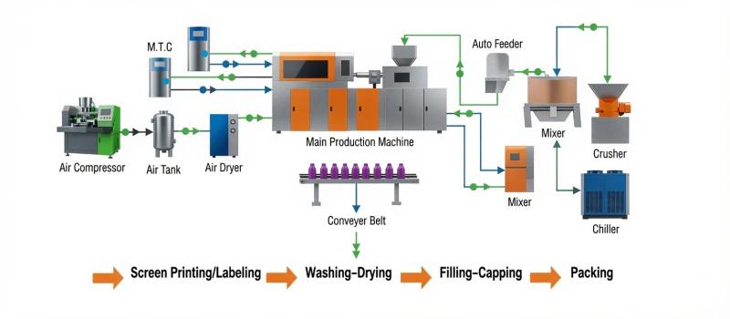
The most common cause of commissioning delays is inadequate site preparation — the machine arrives and installation cannot begin because utilities are not ready, the floor is not rated for the machine weight, or access routes are insufficient for the machine dimensions. All site preparation should be completed and verified at least one week before the scheduled machine delivery date.
Floor Load Capacity
IBM machines are heavy, concentrated loads. The floor must be rated for the machine’s static weight plus dynamic loading from machine motions, plus the weight of the mould tooling, hopper dryer, and operator access platforms. Minimum floor load ratings by machine model:
| Machine Model | Machine Weight | Footprint (L x W) | Min Floor Rating | Notes |
|---|---|---|---|---|
| ZQ40 | 3.5 T | 2.8 x 1.6 m | 10 kN/m² | Standard industrial floor typically adequate; verify with structural engineer if floor age or condition is uncertain |
| ZQ60 | 5.0 T | 3.2 x 1.8 m | 12 kN/m² | Allow 1.5 m clearance on operator side and 1.0 m on rear for maintenance access |
| ZQ60HE | 6.0 T | 3.4 x 1.9 m | 14 kN/m² | Heavier than hydraulic ZQ60 due to servo motor assemblies; verify floor at all four machine feet positions |
| ZQ80 | 10 T | 4.0 x 2.2 m | 18 kN/m² | Large machine — structural floor assessment recommended for any floor below 200 mm reinforced slab specification |
Utilities Requirements Checklist
Electrical Power
Three-phase supply at 380V or 415V (confirm machine specification) with neutral and earth. Supply rated for machine nameplate kVA plus 25% headroom. Dedicated isolator at machine position. Cable tray route from distribution board to machine confirmed and clear. Earth continuity verified. For ZQ60HE: servo drive harmonic loading may require power conditioning if supply quality is poor — confirm with machine electrical specification.
Cooling Water
Supply and return manifolds at machine position, capable of supplying the required total flow rate for all mould cooling circuits plus hydraulic oil cooler (for hydraulic machines). Minimum supply pressure: 3 bar gauge. Flow capacity: 30 to 60 litres per minute depending on machine model and mould circuit count. If chilled water is planned (recommended for cycle time optimisation), chiller unit installed and commissioned before machine startup. Water quality: pH 7 to 9, hardness below 150 ppm to prevent scaling in mould channels.
Compressed Air
Blow air supply at 0.6 to 1.0 MPa (6 to 10 bar), dry and oil-free, at sufficient flow capacity for all simultaneously blowing cavities. For pharmaceutical applications: blow air must be pharmaceutical-grade (filtered to 0.01 micrometre, oil content below 0.01 mg/m³, dew point below minus 40 degrees C). Standard industrial compressed air is not acceptable for pharmaceutical IBM production without downstream filtration and drying.
Hopper Dryer
Dryer mounting platform or structure above machine barrel throat confirmed. Dryer electrical supply separate from machine supply (dryer has independent thermal management). Return air duct to desiccant wheel confirmed clear. For desiccant dryers: desiccant regeneration heater electrical supply confirmed. Dryer commissioned and verified at target dew point (below minus 40 degrees C) before first resin loading.
The delivery day checklist: On the day of machine delivery, the following must be confirmed before the machine is unloaded from the delivery vehicle: (1) Floor area is clear and accessible for the machine footprint plus 2 m around all sides; (2) Fork-lift or overhead crane capacity is confirmed adequate for the machine weight at the delivery access point; (3) All utility termination points are within 3 m of the machine position and labelled; (4) The machine installation drawing has been reviewed and the machine orientation (operator side position relative to production flow direction) has been confirmed with the production team. Delays discovered after the machine is on the production floor are far more costly to resolve than delays discovered before unloading.
2. Machine Installation: Levelling, Anchoring, and Utilities Connection
IBM machine installation requires more precise levelling than standard industrial equipment because the rotary table alignment is sensitive to machine frame twist and tilt. Even small levelling errors (above 0.5 mm/m) can produce table wobble that affects parison transfer accuracy and container dimensional consistency.
Step 1: Position and rough-level
Position the machine on its levelling feet at the designated floor position. Using a precision spirit level (minimum 200 mm length, 0.02 mm/m sensitivity), rough-level the machine frame to within 1.0 mm/m in both the X and Y directions by adjusting the levelling foot heights. Check levelness at the machine bed (injection platen mounting surface) and at the rotary table bearing housing — these are the two critical reference surfaces for IBM machine levelling, not the machine base frame.
Step 2: Fine-level to tolerance
Fine-level the machine to within 0.2 mm/m in both directions. For IBM machines, the critical levelness specification is the parallelism between the injection platen face and the rotary table face at the injection station — these must be parallel within 0.1 mm measured across the platen width. Use a dial gauge on a magnetic base traversed across the platen face to verify this parallelism after final levelling. Record all levelness measurements in the installation record.
Step 3: Floor anchor or vibration isolation
IBM machines can be either anchor-bolted to the floor (preferred for production stability — prevents machine walking under cyclic loads) or installed on anti-vibration mounts (preferred where adjacent sensitive equipment would be affected by machine vibration). For pharmaceutical clean-room installations, anti-vibration mounts are often preferred to minimise vibration transmission through the floor slab. If anchor-bolting, confirm the bolt pattern and embedment depth with the machine installation drawing before drilling.
Step 4: Utilities connection sequence
Connect utilities in the following sequence, verifying each before connecting the next: (1) Earth bonding (must be first — verify earth continuity before any electrical connection); (2) Cooling water — connect, pressurise to 4 bar, and hold for 30 minutes to confirm no leaks before machine electrical connection; (3) Compressed air — connect and verify at machine blow valve inlet; (4) Main electrical supply — connect with machine isolator in OFF position; (5) Dryer electrical supply. Do not energise the machine until all utilities are connected and verified leak-free.
3. Machine Functional Testing Without Mould
Before the mould is installed, all machine functions must be tested in sequence — first in manual mode with individual axis control, then in automatic dry-cycle mode without mould. This approach identifies any installation or machine transit damage before the mould is at risk of damage from a machine malfunction.
Stage A
Control System Power-On
Energise control system only (PLC, HMI, safety relay). Verify all axis position sensors show correct home position. Check all E-stop circuits function (E-stop button, safety gate interlock, light curtain if fitted). Confirm alarm history is clear. Do not energise drive systems until all safety circuits are confirmed functional.
Stage B
Drive System Verification
Energise drive systems (hydraulic power unit or servo drives). For hydraulic machines: verify hydraulic pressure builds to setpoint without leaks; check oil temperature; verify all valve actuation in manual mode. For ZQ60HE: verify servo drive enable signals; check encoder feedback on each axis; confirm all axes home to position sensors correctly.
Stage C
Individual Axis Testing (Manual Mode)
Test each machine axis individually in manual mode at low speed: injection advance/retract, clamping open/close, table index (single step), blow open/close, stripping advance/retract, screw rotation. Verify each axis moves smoothly without binding, reaches its end position and triggers the correct position sensor, and returns to home position without fault. Document each axis pass/fail.
Stage D
Barrel Heat-Up and Purge
Set barrel zone temperatures to the initial process parameter set for the resin. Allow 45 to 60 minutes for full thermal stabilisation. Verify all zone temperatures reach setpoint within plus or minus 5 degrees C. Load resin into the dryer hopper (after confirming dryer is at setpoint). Run the first purge: 5 to 10 shots of resin through the nozzle at low injection speed with no mould present. Examine purge material for contamination, discolouration, or moisture streaks.
Stage E
Dry Cycle Verification
Run the machine in automatic mode with no mould for 20 to 50 cycles. Measure the dry cycle time on the machine display and compare to the machine specification for the model. Verify no axis faults occur during dry cycling. Check for unusual noise, vibration, or heat generation at any axis. Confirm table index repeatability by observing that the table stops at the same angular position each cycle (mark with a reference line and verify visually).
Do not skip the dry cycle stage: The instinct when a new machine arrives is to install the mould as quickly as possible and start making containers. Resisting this instinct and completing the full functional test sequence without the mould installed is one of the highest-value commissioning disciplines. The mould represents significant capital (typically USD 15,000 to 60,000 for a multi-cavity pharmaceutical IBM mould set) and can be damaged by machine malfunctions that would be harmless in a no-mould dry cycle test. The 4 to 8 hours spent on functional testing without the mould is insurance against mould damage events that could delay commissioning by 4 to 8 weeks for tooling repair.
4. Mould Installation and Alignment: The IBM-Specific Requirements
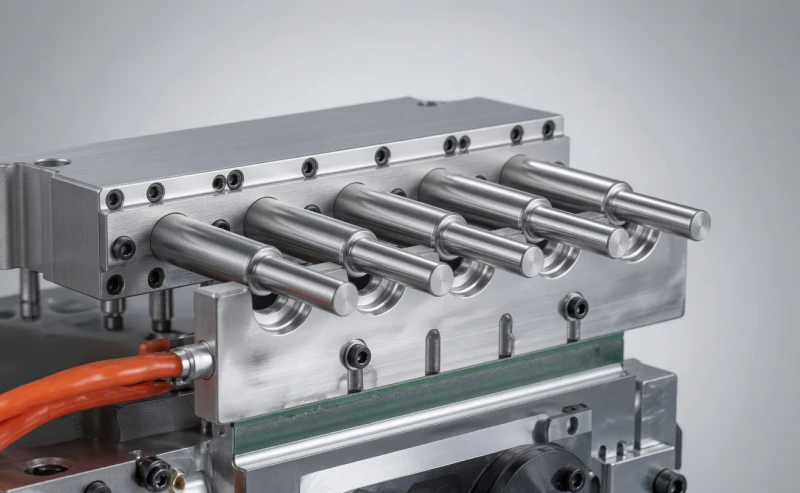
IBM mould installation requires aligning three separate tooling sets simultaneously — the injection cavity block, the core pin array (on the rotating table), and the blow cavity block — so that the core pins enter and exit each cavity at precisely the correct position. Misalignment at any station produces core pin contact damage, cavity scratching, and dimensional variation in the finished container.
The IBM Mould Installation Sequence
Install core pin array on rotary table
Mount the core pin carrier plate on the rotary table using the specified torque on all mounting bolts. Verify the core pin heights are consistent — all core pin tips must be at the same height above the table face within 0.05 mm. Measure using a height gauge referenced to the table face. Install the blow air manifold and confirm the blow air connection port aligns with the machine’s blow air supply port.
Install injection cavity block on injection platen
Mount the injection cavity block on the injection platen using the locating ring and mounting bolts. Verify the cavity centrelines align with the core pin centrelines — use a dial gauge on the platen to measure the offset between the core pin centre positions (measured with table indexed to injection station) and the cavity bore centres. Adjust the cavity block position using the locating ring until concentricity is within 0.1 mm for all cavities simultaneously. Connect cooling water circuits and nozzle connection.
Install blow cavity block on blow station
Mount the blow cavity block on the blow station. Index the table to bring the core pins to the blow station position. Verify the core pins are centred within the blow cavities — check entry clearance around the core pin at the cavity mouth using feeler gauges or optical measurement. Connect blow cavity cooling circuits and blow air connection at the base of the cavity block.
Verify alignment by slow manual cycle
With machine in manual mode at very slow speed, manually cycle the injection clamp closed and open — the injection cavity must close smoothly around the core pins without contact at any position. Index the table one step and manually cycle the blow clamp closed and open — the blow cavities must close around the core pins without contact. Listen and feel for any mechanical contact during this slow manual check. Any contact indicates misalignment that must be corrected before proceeding to powered cycling.
Mould dry cycle at production speed
Run 20 to 30 automatic dry cycles at production speed with mould installed but no resin injected. Verify all clamp and index motions complete within specified time, cooling water flows are confirmed at each cavity circuit, and no alarms or mechanical contact events occur. Check mould temperature at cavity surfaces after 20 cycles using an infrared thermometer — temperature should be rising toward coolant temperature setpoint, confirming the cooling circuits are active.
5. Initial Process Parameter Development: The Safe-Start Sequence
The initial process parameter set should be developed following a safe-start sequence that progressively moves from conservative settings toward optimal settings, verifying container quality at each step before advancing. Starting at conservative settings prevents mould damage from overloading, prevents container defects that could contaminate the mould, and provides a systematic record of how each parameter affects container quality.
Safe-Start Initial Parameter Set (PP Pharmaceutical Syrup Bottle Example)
The Progressive Parameter Development Sequence
| Development Step | What to Observe | Adjustment if Not Satisfactory | Advance Criterion |
|---|---|---|---|
| First 5 shots: fill only | Parison is completely filled with no short shot or flash; parison surface is smooth without silver streaks | Short shot: increase injection speed 10% or barrel temperature 5°C. Flash: reduce shot size 2% or injection speed 5%. Silver streaks: check resin moisture, increase purging | Consistent complete fill with no surface defects across 5 consecutive cycles |
| Shots 6 to 15: blow and check body | Container body is completely inflated to blow cavity shape; body surface is smooth and glossy; no body distortion after ejection | Incomplete inflation: increase blow pressure to 0.8 MPa. Orange-peel surface: increase blow dwell 0.5 s. Body distortion: increase blow dwell 0.5 s or reduce blow cavity temperature | Consistent complete inflation with smooth body surface and no post-ejection distortion |
| Shots 16 to 30: weight and dimension check | Weigh containers from each cavity; measure neck T, E, I, and H dimensions on at least 2 containers per cavity | Weight below target: increase shot size 1%. Weight above target: reduce shot size 1%. Neck dimensions deviant: refer to neck dimension drift troubleshooting framework | All cavities within 3% weight of each other; all neck dimensions within drawing specification |
| Shots 31 to 50: cycle time optimisation | Step down injection cooling dwell in 0.2 s increments; step down blow dwell in 0.2 s increments; verify quality is maintained at each step | Neck dimension drift or parison drop: cooling dwell is below minimum — return to previous value. Body distortion: blow dwell below minimum — return to previous value | Minimum cycle time identified; all dimensions within specification at the optimised cycle |
| Shots 51 to 100: stability confirmation | Run 50 consecutive cycles at optimised parameters without parameter adjustment. Weigh and measure at cycles 51, 60, 70, 80, 90, and 100. Check for any drift in weight or dimensions across the 50-cycle run | Drift within 50 cycles indicates thermal equilibrium not yet reached or a process stability problem — increase warm-up time or investigate specific drifting parameter | No systematic drift in weight or any dimension across 50 cycles at the optimised parameter set |
6. First Article Inspection: Measuring Against the Container Specification
First Article Inspection (FAI) is the formal measurement of a sample of containers produced at the nominal process parameter set against all dimensions and attributes specified in the container drawing and specification. It is the first definitive answer to the question: does this machine and mould combination produce a container that meets the customer specification? FAI must be conducted with calibrated measurement equipment and documented with recorded results.

FAI Measurement Plan
The FAI sample size and measurement plan should be defined before commissioning begins. A typical FAI plan for a multi-cavity pharmaceutical IBM container:
| Attribute | Sample Size | Measurement Method | Accept Criterion |
|---|---|---|---|
| Container weight | 10 per cavity | Analytical balance, 0.01 g resolution | Mean within plus or minus 3% of target; all individual values within plus or minus 5% of target |
| Neck thread OD (T dimension) | 5 per cavity | Thread plug gauge (go/no-go) and digital outside micrometer | All values within drawing tolerance; go gauge enters freely, no-go gauge does not enter |
| Neck OD (E dimension) | 5 per cavity | Digital outside micrometer or bore gauge at specified measurement height | All values within plus or minus 0.2 mm of nominal (or drawing tolerance if tighter) |
| Neck bore ID (I dimension) | 5 per cavity | Pin gauge or internal micrometer at specified measurement depth | All values within drawing tolerance; dropper tip or syringe adaptor fitment verified functionally |
| Container height (H) | 5 per cavity | Height gauge on flat reference surface | All values within plus or minus 0.5 mm of nominal |
| Body diameter | 5 per cavity | Digital caliper at maximum body diameter position | All values within plus or minus 0.3 mm of nominal |
| Visual appearance | All produced during trial | 100% visual inspection under standard daylight illumination against approved defect reference standard | Zero critical defects (flash at neck, short shots, holes); AQL 1.0 for major defects (silver streaks, significant surface defects) |
| Closure compatibility | 5 per cavity | Functional test with production closure: removal torque, tamper-evidence function, leak test | All closure functions perform to specification; removal torque within specified range; zero leaks at test pressure |
FAI timing — measure at 4-hour stabilisation: Container dimensions change after ejection as residual moulding stresses relax. For PP containers, the majority of post-ejection dimensional relaxation is complete within 2 to 4 hours at room temperature. FAI samples should be measured no earlier than 4 hours after production to reflect the stabilised dimensions the filling line and closure application equipment will encounter. Measuring immediately after ejection and recording these as FAI results is a commissioning error that will create discrepancies when the filling line reports different dimensions from the same containers measured hours later.
7. Process Window Characterisation: Establishing the Validated Range
Process window characterisation determines the range of each process parameter within which the container meets specification — from the lower limit that produces defects at low parameter values to the upper limit that produces defects at high parameter values. The validated process range is then defined as the inner portion of this window, with safety margins from both limits, and is the basis for the IQ/OQ/PQ validation and the ongoing production parameter specification.
Melt Temperature Window
Lower limit: the melt temperature below which short shots, weld marks, or excessive injection pressure occur. Upper limit: the temperature above which discolouration, flash, or excessive shrinkage occurs. Typical PP window: 215 to 260 degrees C. The validated range is set 10 degrees C inside each limit: if lower limit is 218 degrees C and upper limit is 255 degrees C, validated range is 228 to 245 degrees C with a nominal setpoint of 235 degrees C.
Injection Cooling Dwell Window
Lower limit: determined by the cooling dwell step-down trial — the minimum dwell below which neck dimension drift or parison drop occurs. Upper limit: no practical upper limit from a quality standpoint, but cycle time and production economics set a practical upper limit. Validated range: from the empirical minimum plus 0.3 s safety margin to the target cycle time dwell. Document the empirical minimum as a controlled process parameter lower limit, not just a guideline.
Blow Pressure Window
Lower limit: blow pressure below which the parison does not fully contact the blow cavity in all zones, producing surface defects or dimensional non-conformance. Upper limit: set by the machine’s maximum blow air supply pressure (typically 1.0 MPa) and the blow cavity’s structural rating. Typical PP validated range: 0.55 to 0.90 MPa. The window is generally wide for blow pressure — a 10% variation in blow pressure rarely causes quality failure if the minimum is met.
Shot Weight Window
Lower limit: shot weight below which short shots occur in at least one cavity (the cavity with the longest runner path or the smallest gate). Upper limit: shot weight above which flash develops at the parting line of the injection cavity. The window between these two limits defines the shot size tolerance. For pharmaceutical IPC, weight specification is typically plus or minus 5% of target; the machine must be capable of maintaining shot weight within this window across the full production run between calibrations.
The one-parameter-at-a-time rule for process window characterisation: Process window characterisation must vary one parameter at a time while holding all others constant. Varying two parameters simultaneously produces an interaction effect that cannot be attributed to either parameter individually. The IBM commissioning sequence should allow 3 to 5 full production days for process window characterisation on a pharmaceutical container — this time investment is repaid during the IQ/OQ/PQ phases, which proceed much faster when the process window is already well characterised.
8. IQ / OQ / PQ Validation for Pharmaceutical and Food Applications
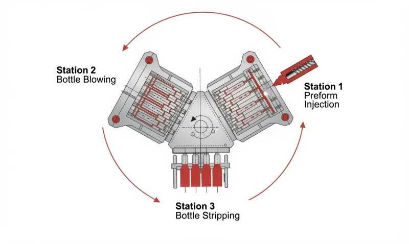
For IBM machines producing containers for pharmaceutical or food applications in regulated markets, formal validation is required — typically structured as Installation Qualification (IQ), Operational Qualification (OQ), and Performance Qualification (PQ). This validation structure maps directly onto the commissioning stages already described, adding formal protocol documentation, data collection, and review/approval steps to each stage.
9. Production Readiness Sign-Off: The Commissioning Completion Checklist
Production readiness sign-off formally closes the commissioning programme and authorises the machine for commercial production. The sign-off requires evidence that all commissioning stages have been completed and documented. The following checklist summarises the minimum evidence required at each stage:
| Commissioning Stage | Evidence Required | Sign-Off By |
|---|---|---|
| Site preparation | Floor load assessment, utilities specification confirmation, access route confirmation | Plant Manager / Engineering |
| Machine installation | Levelness measurement record, utilities connection verification, earth continuity test | Engineering |
| Functional testing | Stage A through E completion record, dry cycle time measurement, safety circuit test record | Engineering |
| Mould installation | Alignment measurement record, manual cycle verification, mould dry cycle record | Process Engineer |
| Parameter development | Progressive development sequence record, nominal parameter set document, 50-cycle stability confirmation | Process Engineer |
| First article inspection | FAI report with all dimensions measured, calibration records for measurement equipment, closure compatibility test results | Quality / Process Engineer |
| Process window characterisation | Parameter window table with limit values, validated range definition, nominal parameter set confirmation | Process Engineer / Quality |
| IQ / OQ / PQ (pharma / food) | Signed IQ, OQ, and PQ reports with QA approval; Cpk greater than 1.33 confirmed for all critical attributes at all cavities | QA Manager |
| Training completion | Operator training records confirmed for all production staff on new machine; IPC procedure signed off and available at machine | Production Manager |
| Production readiness sign-off | All above stages confirmed complete; approved nominal process parameter set document filed; maintenance schedule established; spare parts inventory confirmed | Plant Manager / QA |
10. Frequently Asked Questions
Q: How long should we allow for commissioning a new ZQ60HE with a 6-cavity pharmaceutical mould?
For a new ZQ60HE installation with a 6-cavity pharmaceutical PP container mould and a full IQ/OQ/PQ validation requirement, a realistic commissioning timeline is 6 to 10 weeks from machine delivery to PQ completion and production readiness sign-off. The breakdown is approximately: site preparation (should be complete before delivery — 0 days after delivery); machine installation and functional testing — 3 to 5 days; mould installation and initial parameter development — 3 to 5 days; FAI and process window characterisation — 5 to 10 days; IQ protocol execution and review — 5 to 7 days; OQ protocol execution and review — 5 to 10 days; PQ (three batches plus review) — 7 to 14 days. Teams who have completed IBM commissioning before and have established protocols for each stage consistently complete in 6 weeks. Teams commissioning for the first time typically take 10 to 14 weeks due to protocol development time and review cycles. Developing protocols before machine delivery is the single most effective action for compressing this timeline.
Q: The first article inspection shows neck dimensions within specification for 5 cavities but one cavity is consistently 0.15 mm below the lower specification limit on the I dimension (neck bore). What should we investigate?
A single cavity with a narrow neck bore (small I dimension) at FAI almost always indicates one of three causes: (1) The core pin for that specific cavity position is slightly oversize — measure the core pin diameter at the neck bore zone with a calibrated gauge and compare to specification. A 0.10 to 0.15 mm core pin oversize would produce exactly the observed result. This is a tooling manufacturing issue, not a process issue; (2) That cavity’s cooling channel is blocked or has lower flow rate than the others, causing the parison in that cavity to be hotter during index and distorting the neck bore inward under gravity or index acceleration. Check coolant flow rate per cavity circuit and compare to other cavities; (3) The cavity block mounting position for that specific cavity is slightly different from the others, creating a different core pin eccentricity that affects the available bore diameter. Measure the core pin centring within the injection cavity for the affected position and compare to the others. For each of these diagnoses, the corrective action is a tooling correction (regrinding the core pin, cleaning the cooling circuit, or adjusting the cavity block position) — not a process parameter adjustment.
Q: Can we transfer the validated process parameters from a ZQ60 to a new ZQ60HE machine to avoid a full re-validation?
Partial transfer is possible with appropriate justification but a full re-validation bypass is unlikely to be accepted by pharmaceutical QA or regulators. The ZQ60 and ZQ60HE have the same container output specification for the same container but have different drive architectures (hydraulic versus all-electric), different dry cycle times (4.0 s versus 2.5 s), different injection speed profiles (hydraulic proportional valve versus servo direct drive), and different clamping force control (fixed 600 KN versus variable 400 to 800 KN). These differences affect the process dynamics even when the nominal parameter setpoints are the same. In pharmaceutical validation, a new machine installation requires at minimum a new IQ (always) and a new OQ (machine behaviour verification). Whether the PQ from the old machine is transferable depends on whether the container produced on the new machine is demonstrably equivalent to the container from the old machine — which can be established by a comparability study comparing containers from both machines across all critical quality attributes. If the comparability study demonstrates equivalence, a simplified PQ (one batch rather than three) may be acceptable with appropriate QA review and regulatory assessment. Discuss the transfer strategy with your QA team and, if applicable, with your regulatory affairs team before committing to a simplified approach.
Q: What spare parts should be stocked at machine installation to prevent production stoppages in the first year?
The recommended first-year spare parts inventory for an IBM machine installation covers the components most likely to require replacement during the break-in period and normal production: (1) Hydraulic machines: complete hydraulic seal kit for injection cylinder, clamp cylinder, and table drive motor; one hydraulic pump seal kit; two hydraulic filter cartridges; two barrel heater elements per zone; one set of thermocouple sensors; (2) All-electric machines (ZQ60HE): one servo drive unit for each axis type (one injection drive, one clamp drive — these are typically identical units); encoder cables for each axis; one set of barrel heater elements; one set of thermocouple sensors; (3) All machines: one complete core pin set (or minimum two core pins per cavity size in the active mould); one injection nozzle tip; check valve assembly; one screw tip and ring assembly; one barrel purging compound (2 kg). The investment in this first-year spare parts inventory typically pays for itself through prevention of one avoidable production stoppage of 1 to 3 days duration during the first 12 months of operation.
11. Conclusion
IBM machine commissioning is a defined engineering programme, not a series of adjustments made until the machine works. The sequence from site preparation through production readiness sign-off is the same for every IBM installation — what varies is the depth and formality of documentation required at each stage, which scales with the regulatory requirements of the application. A cosmetic container IBM installation may complete commissioning in two weeks with a first article inspection and a nominal process parameter set. A pharmaceutical container IBM installation in a GMP facility requires six to ten weeks to complete the full IQ/OQ/PQ validation programme.
The stages most commonly compressed or skipped — with the most expensive consequences — are the machine functional testing without mould (skipping this risks mould damage), the FAI dimensional measurement at 4-hour stabilisation (measuring immediately generates systematically incorrect dimensional data), and the process window characterisation before OQ (entering OQ without a characterised window means the OQ protocol may be designed with parameter ranges that do not reflect the actual machine capability).
IBM Commissioning — Key Principles
Complete all site preparation — floor load assessment, utilities installation, access verification — before machine delivery date. Delays discovered on delivery day cost 10x more than delays addressed in advance.
Follow the commissioning sequence without skipping stages. The functional test without mould protects the mould. The FAI at 4 hours protects the dimensional data. The process window characterisation before OQ protects the validation programme integrity.
Record every measurement, every test result, and every parameter set during commissioning. The commissioning records are the foundation of the IQ/OQ/PQ package; reconstructing them after the fact is inaccurate and time-consuming.
For pharmaceutical and food applications, complete IQ/OQ/PQ before commercial production. The production readiness sign-off is a formal gate — commercial product produced before PQ completion does not have a validated manufacturing record and cannot be released to a regulated market.
Our engineering team supports IBM machine commissioning from pre-delivery site review through to IQ/OQ/PQ completion for ZQ-series machine installations. Contact us with your machine model, container specification, and application to discuss commissioning support options and timeline planning.
IBM Commissioning Support
Our applications engineering team provides pre-delivery site review, commissioning engineering support, process development assistance, and IQ/OQ/PQ documentation support for new ZQ-series IBM machine installations. Contact us to discuss commissioning support for your project.