ISBM Machine Troubleshooting: 10 Common Defects and Their Root Causes
ISBM production defects are not random. Every defect has a defined set of root causes — and adjusting parameters without identifying the correct cause first wastes time, material and machine capacity while the actual problem continues. This guide takes a root-cause-first approach to the ten most common defects encountered on one-step injection stretch blow molding machines. For each defect, we identify the physical mechanism behind it, the process variables that cause it, and the corrective actions ranked from fastest to implement to most involved. The emphasis throughout is on ISBM-specific failure modes — many of which differ significantly from those encountered on two-step reheat blow or injection blow molding lines.
1. How to Use This Guide
Each defect entry in this guide follows the same structure: a precise description of the defect as it appears in production, the physical mechanism that produces it, the specific process variables or tooling conditions that cause it, and corrective actions listed in order from fastest to slowest to implement.
Two principles guide every troubleshooting decision on an ISBM line:
1
Change one variable at a timeChanging two parameters simultaneously makes it impossible to determine which change produced the improvement — or the new defect. Run at least 20 cycles after each change before evaluating the result. Impatience is the most common cause of extended troubleshooting sessions.
2
Distinguish preform defects from blow defectsStop the machine in the conditioning station and inspect the preform before it reaches the blow station. If the defect is visible on the preform, the root cause is in the injection station. If the preform is clean but the bottle is defective, the root cause is in the blow station. This single step eliminates half the search space on every troubleshooting exercise.
ISBM vs IBM defects: Many defects on this list have equivalents in IBM troubleshooting guides — but the root causes often differ. In ISBM, the preform retains heat from injection and must be at the correct temperature profile when it reaches the blow station. Temperature-related defects therefore have a thermal history dimension that does not exist in IBM, where the preform is fully cooled and reheated under controlled conditions.
Defect 01 — Bottle Base Haze or Cloudiness
HIGH SEVERITY Visible on: finished bottle base and lower body Station origin: Injection
Description
The finished bottle shows a localised milky or cloudy zone at the base — the area directly above the injection gate. The rest of the bottle body may be clear. In severe cases the haze extends from the base into the lower body. Haze at the base is the most common optical defect in ISBM PETG production and is frequently misdiagnosed as a blow station problem when the root cause is at injection.
Root Causes
▶Gate shear rate exceeding 40,000 s⁻¹: The melt is forced through a gate orifice too small for the shot weight, generating localised frictional heat that degrades the polymer chains. The resulting short-chain fragments scatter light — producing haze that no downstream process can reverse.
▶Moisture in the resin above 0.04% (PETG): Hydrolytic degradation during processing breaks polymer chains and produces volatile by-products that cause internal scattering. Unlike shear haze, moisture haze typically appears throughout the preform — not just at the gate.
▶Barrel temperature too high: Overheating produces thermal degradation that generates acetaldehyde (PET) or discolouration and haze (PETG). Check the actual melt temperature at the nozzle tip with a contact probe — displayed temperature and actual melt temperature often differ by 10–20°C.
▶Contamination from previous resin or purge compound: Incompatible residual material mixes with the current shot and creates localised optical discontinuities at the flow front — typically appearing at the gate zone first.
Corrective Actions
①Verify resin moisture content with a moisture analyser before processing. If above 0.04% for PETG or 0.005% for PET, extend drying time before any parameter changes.
②Reduce injection speed by 15–20% to lower shear rate at the gate without changing gate geometry. Evaluate after 20 cycles.
③Reduce barrel zone temperatures by 5°C increments, starting from the front zone nearest the nozzle. Measure actual melt temperature at nozzle after each adjustment.
④If gate shear rate is confirmed above 40,000 s⁻¹ by calculation, increase gate diameter by 0.2mm — requires tooling modification but is the only permanent resolution for shear-induced haze.
Defect 02 — Uneven Wall Thickness
HIGH SEVERITY Visible on: bottle body cross-section, drop test failure Station origin: Injection or Blow
Description
One side of the bottle body is measurably thinner than the opposite side, or the base is significantly thicker or thinner than the body. The defect manifests as drop test failures on the thin side, visible distortion under internal pressure, or rejection during automated wall thickness scanning. It can affect all cavities identically (systematic cause) or individual cavities only (tooling cause).
Root Causes
▶Core pin misalignment (eccentric preform): If the core pin is not centred within the injection cavity, the preform wall is already uneven before stretching begins. The thinner preform side stretches further and produces a thinner finished wall on that side.
▶Incorrect preform temperature profile at blow station: If one side of the preform is cooler than the other when it reaches the blow station — due to asymmetric mold cooling or inadequate conditioning time — the cooler side resists stretching and remains thick while the warmer side stretches thin.
▶Stretch rod misalignment at blow station: A stretch rod that is not centred within the blow cavity will push the preform material towards one side of the mold during axial extension, creating a systematic wall offset that is consistent across all cycles.
▶Incorrect preform length-to-diameter ratio: A preform designed too short for the bottle requires excessive radial stretch with insufficient axial stretch, concentrating material at the base and leaving the shoulder thin. Requires preform design change.
Corrective Actions
①Measure the wall thickness of a stripped preform (before blowing) at four quadrant points using an ultrasonic gauge. If the preform itself is already eccentric, the root cause is at the injection station — not blow. Check core pin concentricity.
②If the preform is uniform but the bottle is not, check stretch rod alignment within the blow cavity by placing a sheet of carbon paper between the rod and cavity during a slow manual cycle.
③On 4-station machines, increase conditioning time by 0.5s increments to allow better preform temperature equalisation before the blow station.
④Check cooling water flow rates and temperatures at each cavity independently — blocked or partially blocked cooling channels create localised cold spots that cause asymmetric preform temperature.
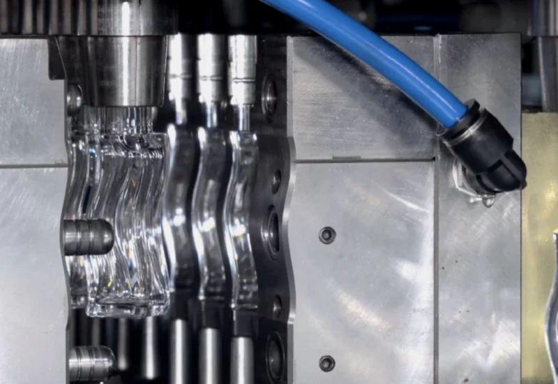
Fig. 1 — Core pin alignment within the injection cavity directly determines preform wall uniformity. A core pin offset of as little as 0.05mm creates a measurable wall thickness variation in the finished bottle. Checking concentricity is the first diagnostic step for any wall thickness defect that appears consistent across all cycles.
Defect 03 — Neck Distortion or Out-of-Round Finish
CRITICAL Visible on: neck thread, sealing surface, closure fit Station origin: Injection / Transfer
Description
The bottle neck is out-of-round, the thread profile is incomplete, the sealing surface is deformed, or closures cross-thread or fail to seal. This is a critical defect that causes leakage in filling lines and returns from customers. It is exclusively an injection-station or transfer defect — the neck is never touched at the blow station.
Root Causes
▶Insufficient neck ring cooling: The neck geometry is not fully solidified before the turntable indexes to the next station. The centrifugal forces and mechanical contact during transfer deform the softened neck. This is the most common cause and is directly observable — the preform neck will be visibly deformed or soft to the touch immediately after injection if cooling is inadequate.
▶Worn or damaged neck ring surfaces: The precision sealing surfaces and thread profiles in neck rings are subject to wear over production cycles. Worn rings produce incomplete or undersized thread profiles that worsen progressively over time.
▶Neck ring opening before full solidification: If the machine attempts to open the neck ring retainer plate before the neck is solidified — due to a short cooling time setting or a cycle timing error — the unsupported neck deforms under the forces of the opening mechanism.
▶Injection temperature too high: Excessively hot melt requires longer cooling time to solidify the neck to the release temperature. If cycle time is not adjusted when temperature increases, the neck arrives at transfer in a semi-soft state.
Corrective Actions
①Reduce neck ring cooling water temperature by 3–5°C. Verify cooling water flow rate at the neck ring inlet — minimum 3 L/min per cavity.
②Increase injection station cooling time by 0.5s increments until the neck is firm to the touch immediately after mold opening.
③Inspect neck ring surfaces under magnification for wear on the thread profile and sealing surface. Replace rings that show measurable wear against the reference dimension on the tooling data sheet.
④Reduce barrel temperature by 5°C increments if the melt temperature is running above specification for the resin grade.
Defect 04 — Short Blow (Underfilled Bottle Body)
HIGH SEVERITY Visible on: bottle body — flat panels, rounded shoulders Station origin: Blow
Description
The bottle body has not fully expanded to the mold cavity dimensions. Flat panels on the body appear convex rather than flat or slightly negative, shoulder radius is larger than specification, and the bottle volume is measurably below target. In severe cases the body has a distinctly oval cross-section in a cavity that should produce a round bottle.
Root Causes
▶Insufficient blow air pressure: The most common cause — blow pressure falls below the minimum required to force the preform fully against the mold cavity wall. This may be caused by an undersized or overloaded air compressor, a leak in the high-pressure circuit, or a pressure regulator set incorrectly after maintenance.
▶Preform temperature too low at blow station: A preform that is cooler than the optimal stretch window resists radial expansion even at correct blow pressure. On a 3-station machine this is more common, as there is no conditioning station to equalise preform temperature before blowing.
▶Blow time too short: Insufficient time at full blow pressure does not allow the material to fully conform to the mold surface before the pressure is exhausted. The bottle springs back slightly on ejection.
▶Pre-blow pressure too high: Counterintuitively, excessive pre-blow pressure can lock the preform into a shape before full axial stretch is complete, preventing complete radial expansion in the lower body during the main blow phase.
Corrective Actions
①Check actual blow station air pressure with a calibrated gauge at the blow valve inlet — not the machine display. Pressure drop between supply and valve indicates a supply or circuit problem, not a machine setting problem.
②Increase main blow pressure by 0.2 MPa increments up to the maximum rated pressure for the mold and machine. If short blow persists at maximum pressure, the root cause is not pressure.
③Extend blow hold time by 0.3s increments. Adequate hold time is reached when further extension produces no change in bottle dimensions.
④On 3-station machines, reduce injection cooling time slightly (0.3s) to allow the preform to arrive at the blow station at a higher temperature. Monitor neck quality closely — neck geometry must remain acceptable.
Defect 05 — Stress Whitening on Shoulder or Body
MEDIUM-HIGH Visible on: bottle shoulder transition and upper body Station origin: Blow
Description
A localised opaque white zone — distinct from haze — appears at the shoulder of the bottle or in the body at a geometric transition point. Stress whitening in PETG and PC is caused by crazing: a network of micro-voids within the polymer that forms when the material is stretched beyond its strain limit. It is a structural concern as well as an optical one — crazed zones have reduced impact resistance.
Root Causes
▶Stretch ratio exceeding the resin’s natural draw ratio: The local stretch ratio at the shoulder transition has exceeded the limit at which the polymer can orient without crazing. This is a design problem — the preform is too short relative to the bottle height, creating excessive axial stretch at the shoulder.
▶Preform temperature too low at the whitening zone: Material that is too cold when stretch begins has insufficient chain mobility to orient — it crazes instead of stretching. The whitening zone corresponds to the coldest point of the preform at the time of blowing.
▶Excessive holding pressure in injection: Over-packed preforms have high residual internal stress. When this stress is released during the stretch blow phase, it can exceed the local crazing threshold at geometric transitions.
Corrective Actions
①Increase preform temperature at the problem zone — on 4-station machines, extend conditioning time by 0.5s. On 3-station machines, reduce injection cooling time by 0.3s and monitor neck quality.
②Reduce holding pressure by 10% increments to relieve residual stress in the preform.
③If stress whitening persists after process adjustments, review preform length — a longer preform reduces the axial stretch ratio at the shoulder and is frequently the only complete resolution for geometry-driven crazing.
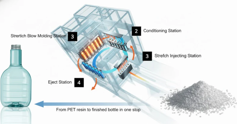
Fig. 2 — Identifying which station originated a defect is the first and most important diagnostic step. Stopping the machine at the conditioning station and inspecting the preform eliminates either the injection or the blow station as the root cause — halving the troubleshooting search space on every defect investigation.
Defect 06 — Sink Marks on Preform Body
MEDIUM Visible on: preform body or finished bottle surface Station origin: Injection
Description
Depressions or dimples on the outer surface of the preform body, visible to the naked eye or by reflected light. In the finished bottle these appear as visible surface distortions that are most obvious under directional lighting — a major aesthetic defect for premium cosmetic bottles.
Root Causes and Corrective Actions
▶Insufficient holding pressure — polymer shrinks away from the cavity wall as it cools. Increase holding pressure by 10% increments until sink marks disappear. The gate must not yet be frozen for holding pressure to be effective — verify gate freeze time by progressive holding time extension.
▶Holding time too short — pressure is released before the gate freezes, allowing material to flow back. Extend holding time in 0.5s increments. The correct holding time is reached when further extension produces no change in sink mark depth.
▶Melt temperature too high — high temperature increases volumetric shrinkage on cooling, demanding more holding pressure compensation. Reduce barrel temperature by 5°C increments.
Defect 07 — Weld Lines on Bottle Body
HIGH SEVERITY Visible on: bottle body — vertical line on side wall Station origin: Injection
Description
A visible line running vertically up the bottle body, often with a slight colour difference or surface step. The weld line is present in the preform and becomes more pronounced after stretching. It represents a weak plane in the bottle wall — drop impact strength is reduced at this location by up to 40%.
Root Causes and Corrective Actions
▶Two melt fronts meeting after flowing around the core pin — increase melt temperature by 5°C to improve molecular bonding at the weld front. Increase injection speed to raise the melt front temperature at the point of convergence.
▶Mold temperature too low at the weld zone — increase cavity cooling water temperature by 3–5°C at the zone corresponding to the weld line location. Warmer mold walls slow melt front cooling and improve weld quality.
▶Unbalanced gate design — if the weld line persists despite parameter optimisation, review the gate position relative to the core pin with a flow simulation. A gate offset that creates unequal flow path lengths around the core pin produces a weld line at the longer path convergence point.
Defect 08 — Gram Weight Variation Between Cavities
MEDIUM Detected by: weighing individual cavity outputs Station origin: Injection
Description
Bottles from different cavities of the same mold weigh measurably different amounts — typically more than ±1.5g variation on a 15–30g preform. Heavier cavities produce bottles with thicker walls that may meet visual standards but waste material; lighter cavities produce thinner bottles that fail drop or pressure tests.
Root Causes and Corrective Actions
▶Hot runner fill imbalance — the most common cause in multi-cavity tools. Cavities fed by longer runner paths receive less material than those closer to the manifold centre. Adjust individual hot runner zone temperatures: increase temperature for underweight cavities, decrease for overweight. Adjust in 3°C increments and allow 10 cycles to stabilise before measuring again.
▶Blocked or partially restricted hot runner nozzle — carbonised resin or contamination partially blocks one or more nozzle tips, reducing flow to those cavities. Remove, clean or replace affected nozzle tips.
▶Core pin height variation between cavities — if one core pin is set lower than others, its cavity receives more material for the same injection volume. Re-check all core pin heights against the reference dimension.
Defect 09 — Bottle Body Distortion After Ejection
MEDIUM Visible on: ejected bottle body — oval cross-section, lean Station origin: Blow / Ejection
Description
Bottles that are dimensionally correct at the blow station develop a distorted body — typically an oval cross-section or a lean to one side — after ejection and cooling. The distortion worsens with ambient temperature and is more pronounced in thick-walled or wide-diameter bottles.
Root Causes and Corrective Actions
▶Insufficient blow cooling time — the bottle is ejected before it has cooled below the resin’s heat distortion temperature. Increase blow hold and cooling time by 0.5s increments until distortion disappears. The minimum cooling time is reached when the ejected bottle body is below 50°C at the thickest wall point.
▶Blow mold temperature too high — mold surface temperature above 20°C for PET or 25°C for PETG results in inadequate heat removal from the bottle wall during the blow hold phase. Reduce chilled water setpoint by 3°C increments and verify actual mold surface temperature with an infrared thermometer.
▶Asymmetric blow mold cooling channels — one side of the blow mold runs warmer than the other due to partial blockage or different flow rates. The warmer side releases a softer bottle wall that distorts on ejection. Measure mold surface temperature at multiple points to identify asymmetry.
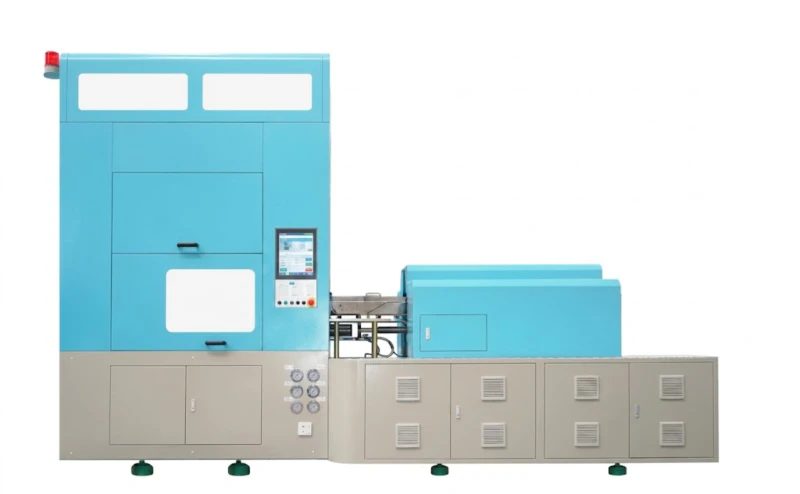
Fig. 3 — The HGY150-V4-EV blow station. Blow-station defects — short blow, body distortion, stress whitening — are all diagnosed and corrected at this station. The 4-station design separates injection cooling from blow cooling, giving independent control over both thermal stages and significantly expanding the process window compared to 3-station machines.
Defect 10 — Yellowing or Brown Streaks in Preform
HIGH SEVERITY Visible on: preform body and finished bottle Station origin: Injection (Barrel)
Description
A yellow or amber tint appears throughout the preform body, or dark brown streaks appear in the preform that carry through to the finished bottle. In PET, yellowing is accompanied by elevated acetaldehyde (AA) levels that contaminate the bottle contents — a critical concern for food and pharmaceutical applications. In PETG, yellowing indicates chain scission that also weakens the preform.
Root Causes
▶Barrel or nozzle temperature too high: Thermal degradation of the polymer chain. The barrel temperature profile should be verified with a contact thermocouple at the nozzle exit — not from the zone controllers alone. PET degrades above 295°C; PETG above 280°C.
▶Resin residence time too long: Material sitting in the barrel at processing temperature for extended periods — due to slow cycle time, unplanned stoppages or oversized screw relative to shot weight — degrades progressively. Use the minimum barrel size that achieves 90% shot utilisation.
▶Dead spots in the hot runner system: Brown streaks that appear intermittently and then clear suggest carbonised deposits releasing from stagnation zones in the hot runner manifold or nozzle tips. Requires hot runner disassembly and cleaning.
▶Contamination from previous resin: Residual material from a previous production run that was not fully purged can degrade and produce colour at the interface between old and new resin.
Corrective Actions
①Measure actual melt temperature at the nozzle tip with a contact probe. If above the resin’s maximum processing temperature, reduce front barrel zone temperature by 5°C increments.
②For unplanned stoppages exceeding 10 minutes, reduce all barrel zones to standby temperature (typically 30°C below processing temperature) immediately — do not leave the barrel at processing temperature with static material.
③If brown streaks appear intermittently, purge the hot runner with 10–15 purge shots at processing temperature, collecting extrudate. If streaks clear after purging, the cause is a hot runner dead spot — the manifold should be disassembled and cleaned at the next scheduled maintenance window.
④Review screw utilisation — if actual shot weight is below 60% of theoretical barrel capacity, consider reducing the screw diameter to reduce resin residence time.
Quick Reference Diagnostic Table
Use this table at the machine to rapidly identify the most likely cause of a defect before beginning systematic parameter changes.
Defect
First Check
Most Likely Cause
Station
Base haze
Resin moisture content
Gate shear rate / moisture
Injection
Uneven wall thickness
Measure preform wall before blow
Core pin misalignment
Injection / Blow
Neck distortion
Neck ring cooling temp
Insufficient neck ring cooling
Injection
Short blow
Blow pressure at valve inlet
Air pressure drop / low blow time
Blow
Stress whitening
Preform temp at whitening zone
Stretch ratio / low preform temp
Blow
Sink marks
Holding pressure / time settings
Insufficient holding pressure
Injection
Weld lines
Inspect preform for weld line
Low melt temp / low injection speed
Injection
Gram weight variation
Weigh each cavity separately
Hot runner fill imbalance
Injection
Body distortion
Blow mold surface temperature
Insufficient cooling time / mold temp
Blow
Yellowing / streaks
Actual melt temp at nozzle
Overheating / long residence time
Injection
Defect 04 note — air supply as a recurring cause: Short blow caused by insufficient blow pressure is frequently misdiagnosed as a machine parameter problem when it is actually a compressed air supply problem. Before adjusting any machine settings for short blow, install a calibrated gauge at the blow valve inlet and measure actual pressure during the blow phase. A stable oil-free air compressor for ISBM with an adequately sized receiver tank eliminates pressure-drop-induced short blow permanently — no machine parameter adjustment required.
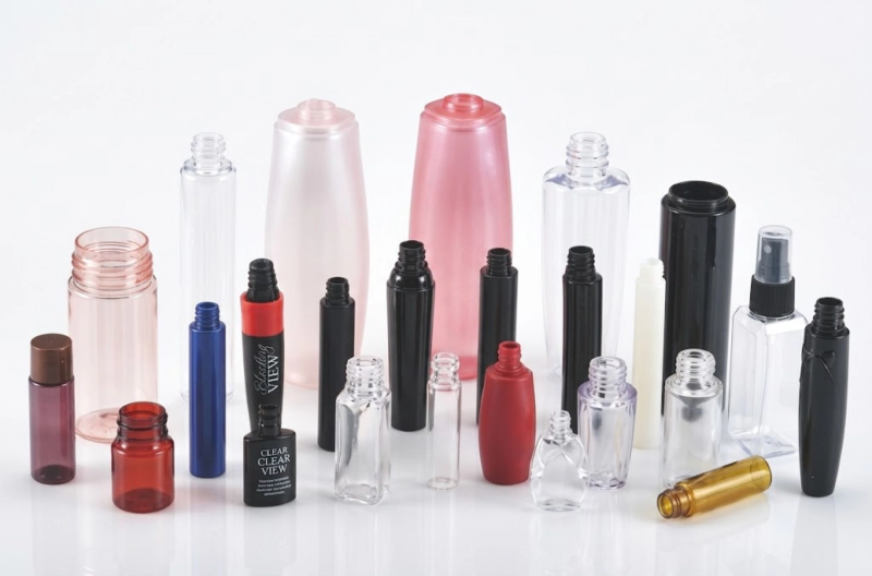
Fig. 4 — Defect-free PETG cosmetic bottles: crystal-clear base, uniform wall distribution, invisible parting line and consistent neck geometry. Achieving this consistently requires not only correct process parameters but a systematic approach to defect diagnosis — identifying the root cause at the correct station before making any parameter changes.
Summary — the three rules of ISBM troubleshooting
1. Locate the station first. Stop the machine at the conditioning station and inspect the preform. If the defect is already present, the cause is at injection. If the preform is clean, the cause is at blow. This single step halves the diagnostic search space.
2. Change one variable at a time. Run 20 cycles after each change before evaluating. Document every change with a timestamp, the old value and the new value. A troubleshooting log that cannot be read by the next shift is not a troubleshooting log.
3. Check the obvious before the complex. Resin moisture, blow air pressure and cooling water temperature account for the majority of ISBM defects. Verify these three before investigating tooling wear, hot runner balance or preform design.
Experiencing a Defect Not Covered Here?
Send us a photo of the defect, the resin grade, the machine model and your current process parameters. Our engineers will identify the root cause and provide a corrective action plan — typically within 24 hours.