
The Most Misunderstood IBM Specification — What Clamping Force Actually Does, How to Calculate What You Need, and Why Getting It Wrong Costs You in Flash, Rejects, and Wasted Machine Investment
When buyers compare injection blow molding machines, clamping force is the number most frequently cited and least well understood. Some buyers treat it as a simple proxy for machine size — bigger number, bigger machine, more capacity. Others conflate it with injection pressure, or assume the highest-tonnage machine is always the safest choice. Both approaches lead to either under-specified machines that flash on injection, or over-specified machines with unnecessary capital cost and energy consumption.
Clamping force in an IBM machine has a specific, calculable mechanical function: it must be large enough to keep the injection cavity parting line sealed against the pressure of the melt filling the cavity. Understanding how to calculate the required clamping force for your specific container, how injection and blow clamping interact, and how our ZQ-series machines are sized across the 400 KN to 1,350 KN range turns a confusing machine specification into a straightforward engineering decision. This guide provides that understanding.
1. What Is Clamping Force and What Does It Do?
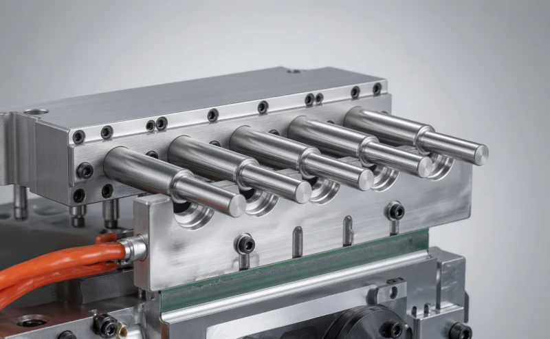
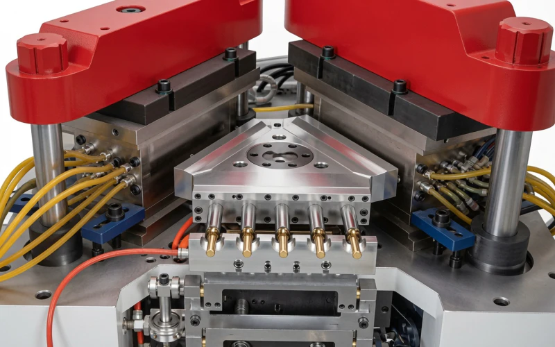
In an injection blow molding machine, clamping force is the mechanical force applied to hold the two halves of a mould cavity together while molten plastic is injected at high pressure inside. Without sufficient clamping force, the injection pressure acting on the projected area of the cavity will force the mould halves apart — and molten plastic will escape through the parting line as flash.
The relationship is simple: the injection pressure inside the cavity pushes outward on the cavity walls. Clamping force pushes inward to keep those walls sealed. When clamping force exceeds cavity pressure force, the mould stays closed and the parison is formed cleanly. When it does not, the parting line opens and flash forms.
Core principle: Clamping force (KN) must always exceed the product of injection cavity pressure (MPa) multiplied by the projected area of the cavity (cm2) times the number of cavities. This is the fundamental equation governing every clamping force specification decision in IBM machine selection.
IBM machines express clamping force in kilonewtons (KN). Our ZQ-series hydraulic IBM machines range from 400 KN (ZQ40) to 1,350 KN (ZQ135). The all-electric ZQ60HE offers variable clamping from 400 to 800 KN, recipe-selectable per product. Understanding which tonnage your specific container requires is the starting point for correct machine selection.
2. Injection Clamping vs Blow Clamping: Two Separate Forces
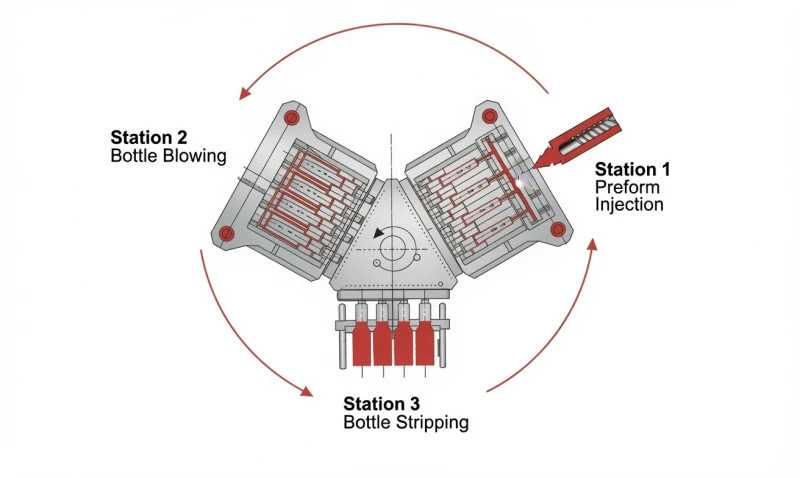
IBM machines have two distinct clamping systems operating at two different stations simultaneously. Buyers and engineers new to IBM often conflate them, but they serve different functions, operate at different pressure levels, and must be sized independently:
Injection Clamping Force
Location: Station 1 (injection station)
Function: Holds injection cavity halves closed during high-pressure melt injection and packing. This is the primary clamping force that determines machine tonnage specification. Injection pressure inside the cavity can reach 60 to 150 MPa, creating enormous separating forces on the cavity parting line.
Magnitude: High. Typically 2 to 5 times larger than the blow clamping force for the same machine.
This is the number quoted as the machine’s “clamping force” (e.g. “400 KN for the ZQ40”).
Blow Clamping Force
Location: Station 2 (blow station)
Function: Holds the blow cavity halves closed during compressed air inflation of the parison. Blow air pressure is typically 0.6 to 1.2 MPa — far lower than injection pressure — so the required blow clamping force is much lower than injection clamping. However, blow cavity projected area is larger than injection cavity area (the finished bottle cross-section is larger than the parison cross-section), which increases the separating force.
Magnitude: Medium. Typically 15 to 30 percent of the injection clamping force for the same machine.
ZQ-series blow clamping: 60 KN (ZQ40) to 200 KN (ZQ135 and ZQ60HE).
| Parameter | Injection Clamping | Blow Clamping |
|---|---|---|
| Opposing pressure | 60 to 150 MPa (melt injection pressure) | 0.6 to 1.2 MPa (blow air pressure) |
| Projected area basis | Parison cross-section (injection cavity) | Finished bottle cross-section (blow cavity) |
| Consequence of insufficient force | Flash on parison body and neck thread | Flash on bottle body parting line |
| Relative magnitude (ZQ40) | 400 KN | 60 KN |
| Relative magnitude (ZQ135) | 1,350 KN | 200 KN |
3. How to Calculate Required Injection Clamping Force
The required injection clamping force is calculated from a straightforward mechanical principle: the separating force on the mould parting line equals the injection cavity pressure multiplied by the total projected area of all cavities in the plane of the parting line.
The Clamping Force Formula
F = P x A x N x SF
F
Required clamping force (KN)
P
Injection cavity pressure (MPa). Use 80 MPa for standard IBM as a starting estimate.
A
Projected area of a single injection cavity in the parting line plane (cm2)
N
Number of cavities in the mould
SF
Safety factor (typically 1.1 to 1.3 — allows for pressure spikes and runner area)
Units note: 1 MPa times 1 cm2 = 100 N = 0.1 KN. So if P is in MPa and A is in cm2, then F in KN = P x A x N x SF x 0.1.
This formula gives the theoretical minimum injection clamping force. In practice, we recommend adding a safety margin of 20 to 30 percent above the calculated minimum to account for:
- Pressure spikes at the end of injection fill phase (momentary pressure can exceed average cavity pressure by 20 to 40 percent)
- Runner system projected area (the sprue and runner channels also occupy parting line area and transmit injection pressure)
- Resin viscosity variation between batches (higher-viscosity batches require higher injection pressure for the same fill speed)
- Temperature variation across production shifts (colder machine startup conditions increase melt viscosity and injection pressure)
Practical rule of thumb: For standard IBM pharmaceutical and cosmetic containers (PP, round, 10 to 500 ml), use 70 to 90 MPa cavity pressure and a 1.2 safety factor. For HDPE agrochemical containers with thicker parisons and wider cross-sections, use 80 to 100 MPa. For PET containers which require higher injection pressures due to higher melt viscosity, use 90 to 120 MPa cavity pressure in the calculation.
4. Projected Area: The Key Variable in the Calculation
The projected area of the injection cavity is the area of the cavity cross-section measured in the plane of the mould’s parting line — the plane where the two cavity halves meet and where flash would form if clamping force were insufficient. This is not the same as the surface area of the parison; it is the shadow area the parison body would cast if light were shone perpendicular to the parting line.
For a round IBM parison with outer diameter D (mm) and height H (mm), the injection cavity projected area is approximately:
A (cm2) = D (mm) x H (mm) / 100
For a round parison: projected area = outer diameter x height, converted to cm2 by dividing by 100.
This simplified formula gives a useful estimate. The actual projected area is calculated by the mould designer from the full cavity geometry, including neck diameter and any shoulder transitions. The key insight is that larger containers and wider parisons have larger projected areas and therefore require higher clamping force.
| Typical Container | Parison OD (mm) | Parison Height (mm) | Approx. Projected Area (cm2) |
|---|---|---|---|
| 5 ml eye drop vial | 12 | 35 | 4.2 |
| 30 ml pharmaceutical vial | 22 | 65 | 14.3 |
| 100 ml cosmetic bottle | 32 | 90 | 28.8 |
| 250 ml PP syrup bottle | 42 | 120 | 50.4 |
| 500 ml water bottle (PET) | 30 | 130 | 39.0 |
| 500 ml HDPE agrochem bottle | 52 | 140 | 72.8 |
| 1,000 ml PP food container | 60 | 170 | 102.0 |
| 2,000 ml HDPE container | 75 | 220 | 165.0 |
The table illustrates why a small pharmaceutical vial (4.2 cm2 projected area) requires very little clamping force per cavity, while a large HDPE agrochemical container (165 cm2) demands much more. Multiplying by cavity count (Section 5) and cavity pressure (Section 6) converts these areas into the required machine tonnage.
5. How Cavity Count Multiplies Clamping Force Requirement
Every additional cavity in the mould adds its projected area to the total separating force on the parting line. The relationship is linear: a 4-cavity mould requires exactly twice the clamping force of a 2-cavity mould for the same container, all else being equal.
This is why cavity count and clamping force are inseparable decisions in IBM machine selection. The maximum economically viable cavity count for a given container on a given machine is determined by the machine’s clamping force divided by the required force per cavity. Buyers who specify too many cavities on an under-powered machine end up with chronic flash problems; those who specify too few cavities on an over-powered machine leave output capacity — and capital productivity — on the table.
Cavity Count vs Required Clamping Force — 30 ml Pharmaceutical Vial (PP, 14.3 cm2 projected area, 85 MPa cavity pressure, SF 1.2)
| Cavities | Total Projected Area (cm2) | Required Clamping Force (KN) | Minimum ZQ Model |
|---|---|---|---|
| 2 | 28.6 | 29 | ZQ40 (400 KN — very comfortable) |
| 4 | 57.2 | 58 | ZQ40 (400 KN — comfortable) |
| 6 | 85.8 | 87 | ZQ40 (400 KN — adequate) |
| 8 | 114.4 | 116 | ZQ40 (400 KN — within spec) |
| 12 | 171.6 | 174 | ZQ40 (400 KN — within spec, check platen) |
| 16 | 228.8 | 232 | ZQ40 (400 KN — within spec, platen check critical) |
| 24 | 343.2 | 348 | ZQ60 (600 KN) |
| 32 | 457.6 | 464 | ZQ60 (600 KN — tight, ZQ80 preferred) |
Calculated using F = P x A x N x SF x 0.1, where P = 85 MPa, A = 14.3 cm2, SF = 1.2. Actual values require mould design verification including runner area.
Important: The platen size constraint is often binding before the clamping force constraint for small containers at high cavity counts. A 16-cavity 30 ml vial mould requires enough platen area to physically fit all 16 cavities in the injection cavity block. Always verify both clamping force adequacy and platen size compatibility when designing high-cavity-count IBM moulds.
6. Resin-Specific Injection Pressure: PET vs PP vs HDPE
Different resins require different injection pressures to fill the same cavity at the same speed, because their melt viscosities differ significantly. Melt viscosity determines how much injection pressure is needed to push the melt through the gate, runner, and cavity at the required fill velocity. Higher viscosity requires higher injection pressure, which increases the separating force on the mould parting line and therefore increases the required clamping force.
.webp)
| Resin | Typical IBM Cavity Pressure (MPa) | Relative Clamping Demand vs PP | Key Reason |
|---|---|---|---|
| PET | 90 to 130 MPa | +20 to +40 percent | Higher melt viscosity (IV-dependent), higher processing temperature, thicker parison walls typical in IBM PET |
| PP | 70 to 95 MPa | Baseline | Good melt flow, wide processing window, standard pharmaceutical IBM reference resin |
| HDPE | 75 to 105 MPa | +5 to +15 percent | Slightly higher viscosity than PP at IBM temperatures; thicker walls and wider parisons for chemical resistance also increase area contribution |
| LDPE | 50 to 75 MPa | -15 to -25 percent | Very low melt viscosity; LDPE eye drop and squeeze bottle containers require less clamping force than equivalent PP containers |
| PETG | 80 to 110 MPa | +10 to +20 percent | Similar to amorphous PET; glycol modification reduces viscosity slightly vs standard PET but processing pressure remains higher than PP |
Design implication: A producer who currently runs PP pharmaceutical containers and plans to add PET containers on the same machine must verify that the machine’s clamping force is sufficient for PET at the same cavity count. PET’s higher injection pressure typically increases the required clamping force by 20 to 40 percent — meaning a machine specified at comfortable margin for PP may be at or beyond its clamping limit for PET with the same mould.
7. ZQ-Series Clamping Force Range: Which Model for Which Container
| Model | Injection Clamp (KN) | Blow Clamp (KN) | Platen (mm) | Typical Best-Fit Applications |
|---|---|---|---|---|
| ZQ40 | 400 | 60 | 480 x 340 | Small pharmaceutical vials (5 to 100 ml, 4 to 16 cavities PP/LDPE); small cosmetic bottles; sample containers; 1 to 1,500 ml single or 2-cavity at larger formats |
| ZQ60 | 600 | 100 | 600 x 390 | Mid-size pharma bottles (100 to 500 ml, 4 to 12 cavities PP); cosmetic 50 to 500 ml; food condiment PP; mid-size PET at lower cavity counts; HDPE 100 to 500 ml agrochemical |
| ZQ80 | 800 | 120 | 800 x 400 | Large pharma bottles (250 to 1,000 ml, up to 8 to 12 cavities PP/HDPE); high-cavity small vial moulds; large PET pharmaceutical containers; 500 ml HDPE agrochemical multi-cavity |
| ZQ110 | 1,100 | 160 | 1,100 x 460 | Large industrial HDPE containers (500 to 2,000 ml, multi-cavity); maximum cavity count pharmaceutical lines; heavy-parison PP food containers (750 to 2,000 ml) |
| ZQ135 | 1,350 | 200 | 1,300 x 500 | Peak-output industrial lines; maximum cavity HDPE agrochemical (1 to 2 L, 4 to 8 cavities); very large PP/HDPE containers; maximum platen utilisation for high output on any IBM format |
| ZQ60HE | 400 to 800 (variable) | 200 | 600 x 420 | All-electric: GMP pharmaceutical lines, high-speed small containers; recipe-selectable tonnage per product; 400 KN for small vials, 800 KN for 500 ml+ pharmaceutical formats |
Selection shortcut: For PP pharmaceutical containers up to 500 ml in volumes up to 12 cavities, the ZQ60 (600 KN) covers most requirements with comfortable margin. For HDPE agrochemical or large PP food containers above 500 ml, or high cavity counts above 12, start from ZQ80 (800 KN) or above. For all-electric GMP pharmaceutical requirements, the ZQ60HE with variable 400 to 800 KN is the preferred choice regardless of container size within the 600 x 420 mm platen envelope.
8. Blow Clamping Force: Why It Is Separate and How to Size It
The blow clamping force calculation follows the same logic as injection clamping — force must exceed the product of blow air pressure times blow cavity projected area times cavity count — but uses much lower pressure values (0.6 to 1.2 MPa blow air versus 70 to 130 MPa injection pressure):
F_blow (KN) = P_blow (MPa) x A_blow (cm2) x N x SF x 0.1
Where A_blow is the projected area of the finished bottle cross-section (larger than the parison cross-section), P_blow is blow air pressure (typically 1.0 MPa for PP/HDPE, 1.2 MPa for PET), and SF is 1.2 to 1.3.
Example: A 500 ml PP bottle with a body diameter of 70 mm and height of 180 mm. Bottle body projected area = 70 x 180 / 100 = 126 cm2. For a 4-cavity mould at 1.0 MPa blow pressure and SF 1.2:
F_blow = 1.0 x 126 x 4 x 1.2 x 0.1 = 60.5 KN
This is well within the 100 KN blow clamp of the ZQ60 — confirming that blow clamping is rarely the binding constraint compared to injection clamping for standard IBM containers.
Blow clamping force becomes more critical for:
- Wide-body containers with large blow cavity cross-sections (e.g. 3 L to 5 L containers with body diameters above 100 mm)
- High blow air pressure applications (PET at 1.2 MPa, or containers requiring higher orientation pressure for barrier performance)
- High cavity count blow moulds where total blow cavity projected area is large
- ISBM applications where the all-electric ZQ60HE’s 200 KN blow clamp (double the hydraulic ZQ60’s 100 KN) supports larger PET container formats
9. What Happens When Clamping Force Is Too Low
Operating an IBM machine with insufficient clamping force for the container and cavity count produces a characteristic and immediately recognisable set of quality failures. Understanding these symptoms helps diagnose whether a clamping force deficit is the root cause when flash or dimensional problems appear in production:
Flash on the Parison Body or Parting Line
The most direct consequence. As injection pressure begins to separate the cavity halves, a thin film of melt escapes through the opening parting line and solidifies as flash. In IBM, this flash appears on the parison body. If the flash extends to the neck thread area, the thread dimensions are compromised and the container fails closure compatibility testing. Parison body flash also means the parison diameter is larger than designed, causing blow fitting problems at Station 2.
Parison Weight Variation and Short Shots
As the parting line opens under injection pressure, some melt escapes as flash rather than filling the parison cavity wall. The remaining parison has less material than designed — a short shot relative to intended weight. This produces inconsistent wall thickness in the blown container, variable container weight, and potentially holes or pinhole failures in thin-wall regions of the blown bottle.
Neck Thread Dimensional Failures
The neck thread is formed at the injection station to injection moulding precision. If the injection cavity parting line opens during fill, the thread form is distorted — diameter increases, thread depth decreases, and the critical “T” (thread outer diameter) and “E” (neck outer diameter) dimensions shift outside tolerance. The result is caps that leak, child-resistant closures that fail torque testing, and dropper fitments that fit imprecisely.
Accelerated Mould Wear and Parting Line Damage
When the parting line opens repeatedly under injection pressure, the parting line faces of the injection cavity experience cyclic loading and impact when the clamp closes back down. Over time, this damages the precision-ground parting line surfaces, widening the gap and worsening flash even at normal injection pressures. A mould that has experienced chronic under-clamping may require regrinding of parting line faces — an expensive and avoidable repair.
Diagnostic question: If you observe parison flash that disappears when you reduce injection speed or pressure — but only partially fills the parison at those reduced settings — this is a classic symptom of clamping force inadequacy rather than a gate, runner, or barrel temperature problem. Reducing injection pressure to stay within the machine’s clamping limit is not the solution; upgrading to adequate clamping tonnage is.
10. What Happens When Clamping Force Is Too High
Over-clamping — specifying or applying more clamping force than the container and cavity require — does not cause container quality failures in the same way under-clamping does. But it does create a different set of problems:
Higher Capital Cost
Larger machines cost more. A producer who runs 30 ml pharmaceutical vials at 8-cavity and specifies a ZQ135 (1,350 KN) when a ZQ40 (400 KN) is more than adequate has paid 3 to 4 times the necessary capital for clamping mechanism and machine frame.
Higher Energy Consumption
A larger machine uses more energy to generate, transmit, and maintain unnecessary clamping force on every cycle. On a hydraulic IBM machine, the clamping circuit consumes power proportional to the force applied — over-clamping means wasted energy on every cycle for the machine’s entire production life.
Mould Stress and Fatigue
Excessive clamping force compresses the injection cavity block beyond its designed contact stress. Over millions of cycles, this can cause parting line bruising on soft steel cavities, reduced venting effectiveness, and — in extreme cases — cavity dimensional distortion. Cavities should be loaded to the minimum clamping force required, not the maximum available.
Larger Factory Footprint
Higher-tonnage machines are physically larger — greater platen area, heavier frame, larger hydraulic power unit. A ZQ135 occupies approximately 3 times the floor area of a ZQ40. In high-cost industrial factory space, the floor area cost of an oversized machine adds to its total-cost-of-ownership throughout its production life.
The correct approach: Specify the machine at 20 to 30 percent above the calculated minimum clamping force requirement. This provides adequate safety margin for pressure spikes, process variation, and potential future cavity count increase, without the capital and operating cost penalties of significant over-specification.
11. Variable Clamping Force: The All-Electric IBM Advantage

Conventional hydraulic IBM machines apply essentially fixed clamping force during production — the hydraulic clamping pressure is set to a value that works for the largest/most demanding container in the machine’s range, and smaller containers are produced with more clamping force than strictly necessary. This wastes energy and increases mould contact stress on smaller container moulds.
The ZQ60HE all-electric IBM machine uses servo motor torque limiting to apply precisely the clamping force specified in each container’s production recipe — from 400 KN to 800 KN, in any increment, recalled instantly when the operator switches products. This variable clamping delivers three practical benefits:
Energy Optimisation Per Product
Small vials run at 400 KN; large containers at 800 KN. The clamping system only consumes servo motor current proportional to the actual force applied — not a fixed maximum. Across a multi-SKU production day, this reduces average clamping energy consumption by 20 to 40 percent versus fixed hydraulic clamping.
Mould Protection on Close
The servo clamping profile can be programmed with slow, low-force closing for the final 5 to 10 mm of mould close stroke — the phase where a mispositioned core pin or contamination could damage the cavity. Only when the mould is confirmed fully closed does the servo ramp to full clamping force. This two-phase close is programmable and recipe-stored.
Instant Changeover Without Pressure Adjustment
Switching from a 5 ml vial (400 KN) to a 500 ml bottle (750 KN) requires no manual hydraulic pressure adjustment — the new clamping force is stored in the product recipe and applied automatically when the recipe is recalled. First-run-right rate after changeover improves, and the risk of running with incorrect clamping force on a new product is eliminated.
12. Worked Examples: Clamping Force Calculations for Real Containers
13. Frequently Asked Questions
Q: Is injection clamping force the same as machine tonnage in injection moulding machines?
The principle is identical, and the calculation methodology is the same as for injection moulding machine tonnage. The difference is that IBM machines have two separate clamping systems (injection and blow) that must both be sized, while standard injection moulding machines have only one. Additionally, IBM injection cavity projected areas are typically smaller than equivalent injection moulding runner systems (IBM produces thin-wall parisons, not fully finished thick-wall parts), so IBM machines of the same tonnage can often run more cavities than an injection moulding machine of the same rating.
Q: Can I run a larger mould on my existing machine by reducing injection speed and pressure?
Technically possible but practically counterproductive. Reducing injection speed and pressure to stay within the machine’s clamping limit means filling the cavity more slowly — which causes the melt front to cool before the cavity is fully filled, leading to short shots, cold weld lines, poor surface finish, and inconsistent parison dimensions. The correct solution is either to match the mould design to the machine’s actual clamping capacity (fewer cavities or smaller parison dimensions), or to upgrade to a machine with adequate clamping tonnage for the desired cavity count and container size.
Q: Does the blow clamping force specification matter for ISBM machines?
Yes, and it matters more for ISBM than IBM because ISBM uses higher blow pressures (1.0 to 2.5 MPa for PET stretch blow versus 0.6 to 1.2 MPa for IBM), and ISBM blow cavities have larger projected areas (the final blown container dimensions) than IBM blow cavities. For one-step ISBM machines producing large-format PET containers above 1.5 L, blow clamping force can become the binding constraint rather than injection clamping. Our engineering team calculates both injection and blow clamping requirements when sizing ISBM machines for large PET container applications.
Q: Will our existing IBM mould fit the clamping unit of a different machine model?
Mould compatibility between IBM machine models requires verification of: platen dimensions (mould must fit within the platen area), tie bar spacing (mould must fit between the tie bars), mould thickness (cavity block height must match the machine’s daylight range), and core pin register dimensions (the core pin mounting interface must match). Our engineering team provides a mould compatibility assessment free of charge — send us your existing mould’s dimensional drawings and we will confirm which ZQ models it is compatible with, or what adaptations are required to transfer it.
Q: How does wall thickness affect clamping force requirement?
Wall thickness affects clamping force through its effect on injection pressure. Thicker parison walls have more volume to fill in the same cavity height, but the melt flows through a larger cross-section — which actually reduces the resistance to flow and can allow lower injection pressure for the same fill speed. Thinner walls are more flow-restricted, requiring higher injection pressure for the same fill velocity, and therefore more clamping force to resist the increased cavity pressure. For precision thin-wall pharmaceutical vials with narrow parison walls (1.5 to 2.5 mm), account for higher injection pressure in the calculation using 90 to 110 MPa rather than the standard 80 to 85 MPa baseline.
14. Conclusion
Clamping force is not a mystery — it is a calculable mechanical requirement that follows directly from the physics of cavity pressure acting on projected area. The formula F = P x A x N x SF gives any engineer a defensible starting point for IBM machine selection, and the three worked examples in this guide demonstrate how to apply it to real pharmaceutical, PET, and agrochemical container scenarios.
Five-Point Clamping Force Selection Summary
Calculate required injection clamping force using F = P x A x N x SF x 0.1 (KN), where P is resin-specific cavity pressure (70 to 130 MPa), A is single cavity projected area (cm2), N is cavity count, and SF is 1.2 to 1.3.
Add 20 to 30 percent to the calculated minimum for pressure spikes, runner area, and process variation.
Use resin-specific cavity pressure: PP 70 to 95 MPa (baseline), PET 90 to 130 MPa (+20 to +40 percent vs PP), HDPE 75 to 105 MPa (+5 to +15 percent vs PP).
Verify platen size constraint independently — for small containers at high cavity counts, platen area is often binding before clamping force.
For multi-product lines, size to the most demanding container in the range — then consider the ZQ60HE all-electric for variable clamping that applies exactly the right force to each product without over-clamping lighter containers.
Our engineering team calculates injection and blow clamping force requirements for every container project at no charge. Submit your container drawing, resin, and target cavity count and we will return a written machine recommendation with supporting clamping force calculation, platen layout sketch, and factory-direct quotation within 24 hours.
Get a Free Clamping Force Calculation for Your Container
Send us your container drawing (or parison dimensions), resin, and target cavity count. Our engineers will calculate the required injection and blow clamping force, recommend the right ZQ model, and provide a factory-direct quotation — within 24 hours, free of charge.