
The Factory Acceptance Test is the last point at which a buyer has unambiguous leverage over a Chinese machine supplier — after the machine ships, problems become disputes about warranty interpretation, international freight logistics and the practical difficulty of returning a 6-tonne machine across 8,000 kilometres. A well-structured FAT transforms this leverage into protection: it establishes a documented, measured baseline of machine performance against agreed criteria before a single bolt is tightened for shipment. A poorly structured FAT — or none at all — is a commitment to discover problems at the worst possible time, in your factory, after installation. This guide provides a complete FAT framework for ISBM machine buyers: what to verify before the production run, how to structure the run itself, what measurements to take from the bottle sample, how to document the results, and what the consequences are of passing, conditional passing and failing the test.
1. What Is a FAT and Why Is It Non-Negotiable for ISBM Buyers
A Factory Acceptance Test is a structured verification procedure conducted at the supplier’s facility before a machine is shipped to the buyer. Its purpose is to confirm — under controlled conditions, with measuring instruments, and against pre-agreed written criteria — that the machine performs as specified in the purchase contract. It is not a demonstration, a showcase or a sales event. It is an engineering verification exercise with defined pass and fail outcomes.
For Russian buyers of Chinese ISBM machinery, the FAT serves a function beyond technical verification. It is the legal and commercial instrument that:
- ✓Establishes a documented performance baseline that forms the reference point for any warranty claim during the machine’s service life
- ✓Confirms that all components specified in the purchase contract are actually present in the machine before it leaves the supplier’s factory
- ✓Triggers the release of the final payment tranche only after confirmed performance — not on a shipment date that the supplier can meet regardless of machine condition
- ✓Provides the operator team with hands-on familiarisation before installation, significantly reducing startup time and first-production scrap at the buyer’s factory
- ✓Resolves technical disagreements at the supplier’s facility, where engineers, components and tools are all available — rather than 8,000 kilometres away
What the FAT is not: A FAT is not a training session (though training may occur around it), not a demonstration run with the best possible conditions (it must use the buyer’s specified mold, resin and production parameters), and not a formality that is signed off after a brief machine startup. A FAT that does not include a minimum continuous production run, bottle measurement and component inspection is not a FAT — it is a factory tour.
2. Before the FAT: Contractual Preparation
A FAT can only verify what has been pre-defined as the acceptance criteria. If the acceptance criteria are not written into the contract before the FAT date is agreed, the supplier has no contractual obligation to meet any specific standard — and the buyer has no contractual basis for rejecting the machine regardless of its performance. The following must be established in the contract before the FAT date is set:
-
1FAT acceptance criteria as a contract annexWrite the specific, measurable acceptance criteria into the contract before signing — not agreed verbally at the factory on the FAT day. Include: minimum continuous run duration, maximum cycle time, minimum BPH, maximum reject rate, bottle dimensional tolerances, gram weight variation limit, and component inspection requirement.
-
2Component schedule as a contract annexList every major component with brand, model number and rated specification. The FAT phase 2 inspection verifies the machine against this list. Any substitution identified during FAT must be rectified before the production run begins — not after shipment.
-
3FAT mold and resin specificationSpecify in the contract which mold is to be used for the FAT production run — ideally the buyer’s own production mold, shipped to the factory in advance. If the buyer’s mold is not available, specify the nearest equivalent by bottle volume, preform weight, cavity count and resin type. The FAT mold cannot be a “demonstration mold” selected by the supplier to minimise cycle time.
-
4Payment trigger linked to FAT outcomeSpecify that the final payment tranche (typically 10–20% of contract value) is released only after a signed FAT acceptance document. The supplier should receive no contractual obligation to ship until the FAT is passed. This single clause converts the FAT from a courtesy gesture into an enforceable obligation.
-
5FAT failure resolution procedureDefine what happens if the machine fails the FAT: the supplier is given a defined rectification period (typically 20 working days), after which a re-FAT is conducted. If the machine fails the re-FAT, the buyer has the right to cancel the order and receive a full refund of deposits paid. Without this clause, a FAT failure creates a dispute with no defined resolution path.
3. Phase 1 — Documentation Review
Documentation review is conducted before the machine is started. Its purpose is to confirm that all required technical documentation is complete, matches the machine being tested, and is in a usable form for the buyer’s maintenance and operations team. A machine delivered without adequate documentation is operationally incomplete regardless of how well it runs during the FAT.
| Document | Required Content | Accept / Reject Criteria |
|---|---|---|
| Operation manual | Complete operating procedures, parameter setting guide, alarm code list, startup and shutdown sequence | Must be in English (or Russian). Must reference this machine model, not a generic series manual |
| Electrical schematic | Full wiring diagrams for all machine circuits, panel layout drawing, cable routing diagram | Must match the as-built machine. Confirm at least two terminal points against the physical machine |
| Hydraulic/pneumatic schematic | Complete circuit diagrams for all fluid power systems with component identification numbers | Must reference actual component model numbers matching the installed hardware |
| PLC programme documentation | PLC software version number, parameter list with factory default values, access level credentials | PLC must be open-access (not locked). Confirm by logging in at operator level and engineering level with supplied credentials |
| Spare parts list | Itemised recommended spare parts with part numbers, quantities and current prices | Must include at minimum: seal kits, heater bands, common sensors and fuses. Parts without supplier part numbers cannot be ordered |
| CE Declaration of Conformity | Signed declaration with machine model, serial number and list of applied harmonised standards | Serial number on declaration must match the machine being tested. Reject if model or serial number does not match |
| Maintenance schedule | Preventive maintenance intervals for all systems, lubrication points and quantities, filter change intervals | Must be specific to this machine model and the installed components, not a generic schedule |
4. Phase 2 — Component Verification
Component verification is conducted with the machine powered off and with access to all panels open. The buyer’s representative works through the component schedule from the purchase contract, physically locating each component, photographing the nameplate or label, and recording the actual brand, model number and specification against the contracted value. Any discrepancy is recorded on the FAT non-conformance report and must be resolved — not deferred — before the production run begins.
4.1 High-Priority Verification Points
- ▶PLC brand and model: Open the main electrical cabinet. Photograph the PLC rack with all I/O modules visible. Confirm brand (Inovance / MiRLE for HGY series) and model number against the contract. Check that the installed firmware version is documented.
- ▶Servo motors — all axes: On full-servo (EV) machines, open each servo drive cabinet and photograph the motor nameplate at each axis. Confirm brand and rated torque match the contract schedule. Count the number of servo axes — for a 10-axis EV machine, verify all 10 are present.
- ▶Turntable servo and reducer: Confirm Japan Yaskawa or WEICHI servo motor on the turntable drive. Confirm Taiwan TSUNTIEN reducer brand on the turntable gearbox — the brand is cast into the housing body.
- ▶Parker pneumatic valves: Locate the pneumatic manifold bank. Parker valves have a Parker logo embossed on the valve body — check each valve on the manifold. Photograph the manifold from an angle that shows the logo clearly on all valves simultaneously.
- ▶YUKEN hydraulic control valve (hydraulic machines): The YUKEN logo is cast into the hydraulic valve body. Confirm model number against the YUKEN product catalogue for the specified pressure rating.
- ▶Barrel heater type: Confirm nano far-infrared heater bands (the contract specification for HGY150-V4 series) by inspecting the heater type marking on each zone. Standard ceramic heater bands look similar from the outside — check the label or ask the engineer to show the product specification sheet for the installed heaters.
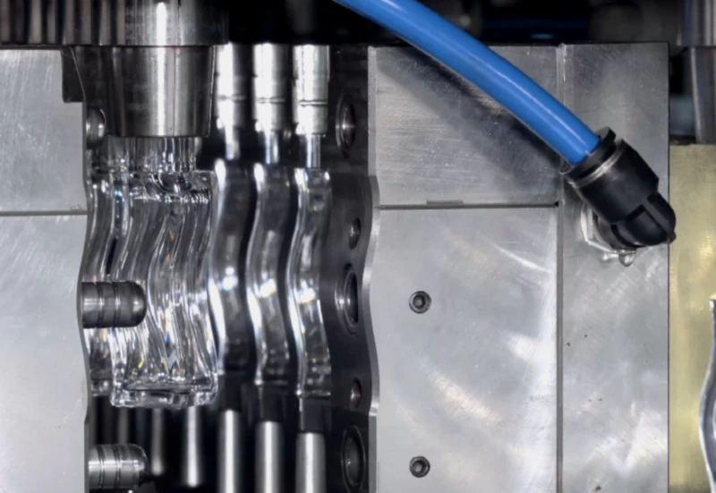
Fig. 1 — Component verification is conducted with the machine powered off and all access panels open. Every major component in the purchase contract schedule is physically located, photographed and recorded against the contracted specification. A component found to be substituted at this stage is a non-conformance that must be rectified before the production run begins — not accepted under a verbal promise to upgrade after delivery.
5. Phase 3 — Mechanical and Electrical Inspection
After component verification and before the machine is powered on for the production run, a physical inspection of the mechanical build quality and electrical installation confirms that the machine has been assembled to an acceptable standard. Mechanical build deficiencies found at this stage are correctable without production downtime; deficiencies discovered after installation at the buyer’s factory require on-site rectification work under much less convenient conditions.
-
AMachine bed and frame alignmentUse a precision spirit level to verify that the machine bed is flat within 0.05mm/m in both axes. A twisted machine bed will cause misalignment of the injection platen, turntable and blow station that worsens under thermal load during production. Corrections require shimming and cannot be made after installation without significant downtime.
-
BCore rod height uniformityUsing a depth gauge referenced from the turntable face, measure the height of each installed core rod tip. Maximum acceptable variation between rods: 0.05mm. A variation above this produces gram weight inconsistency between cavities from the first production cycle. Record the measured height for each rod position on the FAT documentation sheet.
-
CTurntable indexing accuracyJog the machine through 10 complete turntable rotations in manual mode and verify that the station alignment mark returns to the reference position within ±0.1mm at each index. Cumulative indexing error degrades core rod alignment with each station, producing progressive gram weight drift during a production run.
-
DCooling water circuit integrityWith the cooling water connected and pressurised to 0.4 MPa, inspect all connections at the preform mold, blow mold, neck ring circuit and barrel for drips or weeping. A connection that weeps at 0.4 MPa will fail completely under production thermal cycling. Record and rectify all leaks before the production run.
-
EElectrical insulation and cable routingInspect cable routing through the machine frame for cables running across sharp edges, cables not secured in conduit, and cable lengths that are too short to allow the machine to reach its full stroke range without tension. Electrical faults from poor cable routing are the most common cause of random production stoppages in the first 500 hours of operation.
-
FSafety interlocks functional testTest all safety interlocks in manual mode before running the machine: emergency stop function (the machine must stop all motion within 0.5 seconds), guard door interlocks (opening any guard must immediately stop all motion), and injection unit safety guard. A machine with non-functional safety interlocks is a regulatory and liability risk in addition to an operational hazard.
6. Phase 4 — Production Run Protocol
The production run is the centrepiece of the FAT. It must be structured to produce meaningful performance data — not to maximise the likelihood of a pass. The following protocol defines the conditions, duration and measurements required for a valid ISBM FAT production run.
6.1 Pre-Run Setup Requirements
- ✓Resin supplied by or approved by the buyer — not the supplier’s own demonstration resin
- ✓Resin dried to specification (PETG: moisture below 0.04%; PET: below 0.005%) — verified by moisture analyser before loading
- ✓Mold installed and verified against the FAT mold specification from the contract
- ✓All utility supplies connected: compressed air at the contracted pressure, cooling water at the contracted flow rate and temperature, electrical supply at 380V ±5%
- ✓Buyer’s measuring instruments available on-site: calibrated weighing scale (0.1g resolution), digital calipers (0.01mm resolution), contact thermometer for melt temperature, stopwatch, and a three-phase power meter
6.2 Startup and Stabilisation Period
Allow the machine to run for a minimum of 45 minutes from first injection before beginning the formal measurement period. The startup period is not excluded from the FAT timeline — recording the time from first injection to first acceptable bottle (startup time) is part of the FAT data. However, all dimensional and weight measurements are taken from the formal 4-hour measurement period that begins only after the machine has stabilised: stable cycle time, stable gram weight for three consecutive cycles, and stable melt temperature at the nozzle tip.
6.3 Formal Measurement Period
| Measurement | Method | Frequency | Record |
|---|---|---|---|
| Cycle time | Stopwatch — time from one ejection to the next | Every 30 minutes | Mean of 10 consecutive cycles at each interval |
| Total power draw | Calibrated 3-phase power meter at main panel incomer | Continuous log, hourly average | kW average for each logged hour |
| Bottle production count | PLC counter output or manual count | Every 30 minutes | Running total; separate good and reject counts |
| Melt temperature | Contact probe at nozzle tip between shots | Every hour | Must be within ±5°C of target for resin grade |
| Unplanned stoppages | Manual log — note alarm code, time and duration | Immediate on occurrence | Any stoppage > 5 minutes resets the 4-hour clock |
| Gram weight per cavity | Digital scale — weigh one bottle per cavity | Every hour | Mean and range per cavity; max variation ±1.5g |
Air supply during the FAT production run: If the supplier’s factory compressed air system feeds multiple machines simultaneously, verify that the air pressure at the machine’s blow valve inlet remains stable throughout the FAT run. Pressure drops during peak demand periods — when other machines in the factory are also in their blow phase — can cause short-blow defects in the FAT sample that will not occur in the buyer’s dedicated installation. A dedicated oil-free air compressor for ISBM installed specifically for the FAT machine avoids this source of variability and produces results that are more representative of the buyer’s actual installation.
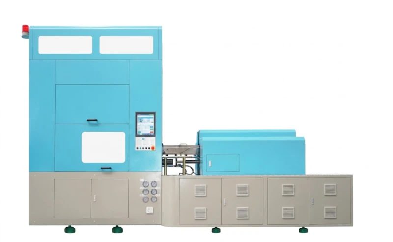
Fig. 2 — The FAT production run must use the buyer’s specified mold, resin and production parameters — not a demonstration configuration chosen to minimise cycle time. Cycle time is measured with a stopwatch every 30 minutes; power draw is logged continuously; bottle production count is tracked separately for good and reject bottles throughout the full 4-hour measurement period.
7. Phase 5 — Bottle Sample Measurement
The bottle sample is collected from the final 30 minutes of the 4-hour production run — the period when the machine has fully stabilised and is most representative of steady-state production. Every bottle produced in the sample period is retained and measured. Sample size: minimum 50 bottles per cavity, collected consecutively without cherry-picking.
7.1 Dimensional Measurements
| Measurement | Instrument | Accept Criterion | Sample Size |
|---|---|---|---|
| Bottle weight (gram weight) | Digital scale, 0.1g resolution | Within ±1.5g of target; max variation cavity-to-cavity ±1.5g | 10 per cavity |
| Neck thread OD | Digital calipers or go/no-go gauge | Within ±0.15mm of standard (GPI / PCO / DIN) | 5 per cavity |
| Neck height | Digital calipers | Within ±0.2mm of drawing specification | 5 per cavity |
| Body outer diameter (max) | Digital calipers — measure at 3 heights | Within ±0.3mm of drawing specification | 5 per cavity |
| Total height | Digital calipers or height gauge | Within ±0.5mm of drawing specification | 5 per cavity |
| Closure fitment test | Production cap or pump — apply and engage by hand | No cross-threading; closure seats fully; no leakage at 0.05 MPa internal pressure | 5 per cavity |
7.2 Visual and Optical Inspection
Visual inspection of the bottle sample is conducted under diffuse natural light and directional artificial light. Inspect each bottle in the sample for the following:
- ✓Base clarity: No haze, cloudiness or yellowing visible at the base in direct light. Any base haze that is visible under normal viewing conditions is a reject.
- ✓Body transparency: No visible haze, streaks or silver marks on the bottle body. The base label area and light-catching shoulder radius must be assessed under directional lighting.
- ✓Stress whitening: No opaque white zones at the shoulder or body. Stress whitening is distinct from haze — it appears as a localised opaque area, not uniform cloudiness.
- ✓Parting line: No visible flash at the blow mold parting line or visible mold seam on the bottle body.
- ✓Neck thread quality: Thread profile complete with no short-fill, no cross-threading marks and no gate flash on the neck finish.
- ✓Body geometry: Bottle stands upright without lean on a flat surface. Base is flat (for round bottles) or within drawing specification for non-round profiles.
8. FAT Acceptance Criteria and Outcomes
A FAT has three possible outcomes: Pass, Conditional Pass and Fail. Each has defined consequences for the commercial relationship and the machine’s shipment status.
PASS — All criteria met
Actual cycle time at or below contract specification; reject rate in sample batch below 1%; all dimensional measurements within tolerances; gram weight variation within ±1.5g between cavities; no unscheduled stoppage exceeding 5 minutes during the 4-hour run; all component nameplates match the contract schedule; all documentation complete and verified.
Consequence: Buyer signs FAT acceptance document; final payment tranche is released; machine is authorised for shipment.
CONDITIONAL PASS — Minor non-conformances only
All critical performance criteria are met (cycle time, reject rate, safety functions) but minor non-conformances exist — for example: one documentation item missing; one component model number slightly different from contract but equivalent specification; one dimensional measurement at the tolerance boundary rather than within it.
Consequence: Buyer signs a conditional acceptance document that lists the non-conformances with agreed resolution dates. Machine may be shipped; final payment held until all non-conformances are closed — typically within 30 days of delivery.
FAIL — One or more critical criteria not met
Cycle time exceeds contract specification; reject rate above 1%; critical component substitution confirmed; unscheduled stoppage exceeding 5 minutes during the run; safety interlock malfunction; bottle dimensional measurements outside tolerances on more than one cavity.
Consequence: Machine is not shipped. Supplier is given the rectification period specified in the contract (typically 20 working days) to resolve all failure points. A re-FAT is then conducted under the same protocol. If the machine fails the re-FAT, the contract cancellation and refund provisions are triggered.
9. Remote FAT: When Video Cannot Replace Physical Presence
Some buyers, particularly during periods when international travel is disrupted or when budget constraints make a factory visit impractical, ask whether a FAT can be conducted by video call. The honest answer is: a video call can replace some elements of the FAT but not the critical ones.
| FAT Element | In-Person | Video Call | Why Video Fails |
|---|---|---|---|
| Documentation review | ✓ | Partial | Documents can be shared digitally but cannot be verified as the actual shipped documentation package |
| Component nameplate verification | ✓ | ✗ | Camera angle and resolution can be controlled; supplier can show correct components in the camera frame without disclosing others |
| Mechanical alignment checks | ✓ | ✗ | Cannot apply instruments remotely; supplier’s own measurement cannot be independently verified |
| Production run observation | ✓ | Partial | Machine startup cannot be independently timed; stoppages may not be disclosed; production count relies entirely on supplier reporting |
| Bottle measurement | ✓ | ✗ | Measurements are performed by the supplier — the party being evaluated. Results cannot be independently verified |
| Safety interlock testing | ✓ | ✗ | Cannot independently verify that observed interlock responses are genuine rather than staged |
If a physical FAT is genuinely impossible, the following partial mitigation is recommended: engage an independent third-party inspection agency with a China presence (SGS, Bureau Veritas, Intertek) to conduct the physical component verification and mechanical inspection on the buyer’s behalf. The agency’s engineers physically locate, photograph and measure components against the specification and report to the buyer independently. This does not replace bottle measurement by the buyer, but it addresses the two highest-risk elements of a remote-only process.
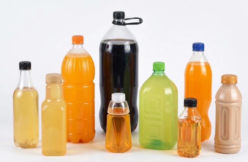
Fig. 3 — Bottle samples from the FAT final 30-minute collection window. These are measured by the buyer’s representative using calibrated instruments brought to the factory — not by the supplier. Gram weight, neck dimensions, body OD and closure fitment results are recorded on the FAT datasheet and become part of the signed acceptance documentation that travels with the machine.
10. Complete FAT Master Checklist
Print and use this checklist on the FAT day. Every item must be completed in sequence. Do not proceed to Phase 4 until Phases 1, 2 and 3 are signed off.
| Phase | Item | Criterion | Pass/Fail |
|---|---|---|---|
| Phase 1 | Operation manual | Complete, in English, matches this model | ☐ |
| Phase 1 | Electrical schematic | Verified against 2 physical terminal points | ☐ |
| Phase 1 | PLC open access | Logged in at both operator and engineering levels | ☐ |
| Phase 1 | CE Declaration serial number | Matches machine serial number plate | ☐ |
| Phase 2 | PLC brand and model | Matches contract schedule — photographed | ☐ |
| Phase 2 | All servo motors (each axis) | Brand, model, rated torque match — all axes photographed | ☐ |
| Phase 2 | Parker pneumatic valves | Parker logo visible on all manifold valves | ☐ |
| Phase 2 | YUKEN hydraulic valve | YUKEN logo cast in body; model number confirmed | ☐ |
| Phase 3 | Machine bed level | Flat within 0.05mm/m in both axes | ☐ |
| Phase 3 | Core rod height uniformity | All rods within 0.05mm of each other — recorded | ☐ |
| Phase 3 | Cooling water circuit | No leaks at 0.4 MPa — all connections inspected | ☐ |
| Phase 3 | Emergency stop function | All motion stops within 0.5 seconds | ☐ |
| Phase 4 | Resin moisture verified | Below 0.04% PETG / 0.005% PET before loading | ☐ |
| Phase 4 | 4-hour continuous run | No stoppage exceeding 5 minutes; cycle time logged every 30 min | ☐ |
| Phase 4 | Actual cycle time | At or below contract specification | ☐ |
| Phase 4 | Power draw recorded | kW average logged hourly from calibrated meter | ☐ |
| Phase 5 | Gram weight per cavity | Within ±1.5g target; max variation ±1.5g cavity-to-cavity | ☐ |
| Phase 5 | Neck thread OD | Within ±0.15mm of closure standard | ☐ |
| Phase 5 | Reject rate | Below 1% in final 30-minute sample batch | ☐ |
| Phase 5 | Visual inspection | No base haze, no stress whitening, no flash, no body distortion | ☐ |
| Phase 5 | Closure fitment test | Production cap seats without cross-threading; seals at 0.05 MPa | ☐ |
| Overall FAT Outcome | Pass / Conditional / Fail | ||
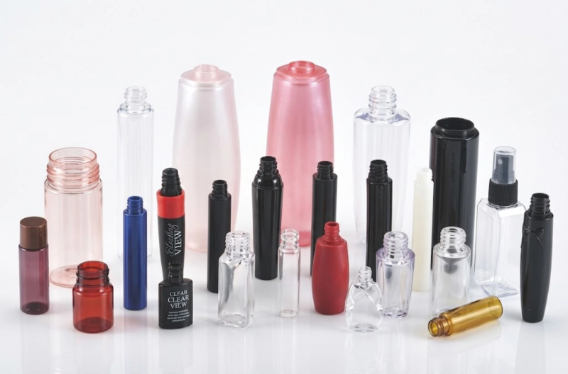
Fig. 4 — FAT-approved PETG cosmetic bottles: on-specification gram weight, correct neck dimensions, closure fitment verified, no visual defects, produced at or below the contracted cycle time for 4 continuous hours. The FAT acceptance document signed against these results is the warranty baseline for the machine’s entire operating life. It is the most important document produced during the entire procurement process.
1. Define the criteria before the FAT date. Acceptance criteria that are not in the contract before the FAT begins are not criteria — they are negotiations. Write every pass/fail threshold into the purchase agreement before signing.
2. Component inspection must precede the production run. A machine that passes the production run but has substituted components has not passed the FAT. Component verification is Phase 2, not an afterthought.
3. Measurements must be taken by the buyer, not the supplier. A supplier measuring their own bottles against their own criteria using their own instruments is not a FAT. Bring your own calibrated instruments and take every measurement yourself.
4. Final payment is released only after FAT acceptance. The financial lever is the only leverage that makes a FAT enforceable. A FAT with no payment consequence is a courtesy visit.
5. Video cannot replace physical presence for critical elements. Remote FAT cannot independently verify component identity or mechanical alignment. Engage a third-party inspection agency for physical verification if travel is impossible.
Ready to Conduct a FAT on Our Machines?
We welcome structured FATs against buyer-defined criteria as standard practice. Factory visits can be arranged with 3 weeks’ notice. We provide full documentation packages, open-access PLC and a dedicated testing bay. Contact us to schedule your FAT date.