
Engineering Deep Dive • Injection Blow Molding Machinery
A rigorous mechanical analysis of IBM clamping dynamics. Discover why relying on marketing “Tonnage Class” labels can lead to catastrophic tool failure, parting-line flash, and GMP compliance issues—and learn the exact mathematical formulas required to size your machine accurately based on projected surface area and cavity pressure.
When packaging manufacturers evaluate capital equipment for a new Injection Blow Molding (IBM) production line, the first specification discussed is almost always the machine’s “Tonnage.” You will frequently hear engineers and procurement officers state that they need a “60-Ton,” “85-Ton,” or “135-Ton” machine. These designations have become the universal shorthand for categorizing machine size, output capacity, and capital cost.
However, this shorthand has created a dangerous oversimplification in the procurement process. A machine’s marketing badge—its “Tonnage Class”—does not always accurately reflect the true, sustained mechanical force it applies across the platen surface during the most critical milliseconds of the injection cycle. Relying solely on the class designation without mathematically verifying the actual Injection Clamping Force (measured in kiloNewtons – kN) against your specific mold layout is a recipe for severe manufacturing defects.
In this comprehensive engineering guide, we dissect the physics of clamping force in the IBM process. We will explore why clamping force exists, how to calculate your exact requirements using projected surface area, why platen deflection matters just as much as peak tonnage, and why utility infrastructure is the silent partner in maintaining clamp stability. By the end of this article, you will possess the analytical framework necessary to select the perfect injection blow molding machine for your operational demands.
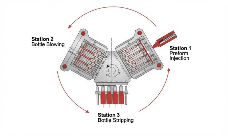
Figure 1: The IBM Three-Station Process. Clamping force is the critical metric at Station 1 (Injection), where immense hydraulic pressure combats the expanding polymer.
1. The Physics of Injection Blow Molding: The Battle of Forces
To understand clamping force, we must first look at what happens inside Station 1 (the Injection Station) of an IBM machine.
During the initial phase of the cycle, molten thermoplastic (such as HDPE, PP, or PCTG) is driven by the extruder screw through a hot runner manifold and injected into the closed steel mold cavities. This is not a gentle pour; the polymer is forced into the microscopic details of the neck ring (to form precision threads) under extreme hydraulic pressure—frequently ranging from 40 MPa to 80 MPa (400 to 800 bar) depending on the resin’s melt flow index (MFI) and the wall thickness of the preform.
According to Pascal’s Principle, this fluid pressure exerts an outward force equally in all directions against the internal walls of the mold cavity. At the exact line where the two halves of the steel mold meet (the parting line), this internal pressure creates a massive Separation Force trying to push the mold open.
Clamping Force is the counter-acting mechanical or hydraulic pressure generated by the machine’s tie-bars and clamping cylinders. Its sole purpose is to exceed the Separation Force, keeping the two halves of the mold hermetically sealed shut until the plastic cools and solidifies.
📐 The Fundamental Formula: Sizing Your Clamp
The theoretical clamping force required to hold an injection mold closed is calculated using the following mathematical relationship:
- $F_{clamp}$: Required Clamping Force (expressed in Newtons or kiloNewtons).
- $A_{projected}$: The total Projected Surface Area of the molded parts and runner system at the parting line (expressed in $cm^2$ or $mm^2$).
- $P_{injection}$: The average cavity pressure during the filling and packing phase (expressed in MPa or bar).
- $S_{safety}$: An engineering safety factor, typically set between 1.15 and 1.30 to account for pressure spikes, resin viscosity variations, and thermal expansion of the tooling.
2. Projected Surface Area: The Metric That Actually Matters
The most common mistake made during machine sizing is looking only at the volume or weight of the bottle rather than its Projected Surface Area. Two different 100ml bottles can require vastly different clamping forces.
Projected surface area is the 2D shadow the preform would cast if a light were shone directly above it, perpendicular to the parting line. It is calculated by taking the maximum width (diameter) of the preform and multiplying it by its length.
Case Study: Cylinder vs. Oval Containers
Imagine you are molding a standard 50ml cylindrical pharmaceutical vial. The preform might have a diameter of 20mm and a length of 60mm. The projected area per cavity is roughly $12 \text{ cm}^2$. If you run a 10-cavity mold, the total cavity area is $120 \text{ cm}^2$ (plus the hot runner manifold drops).
Now, imagine you are molding a 50ml flat, oval cosmetic lotion bottle. The preform must be wider to accommodate the oval blow shape. This preform might have a width of 35mm and a length of 60mm. The projected area per cavity is now $21 \text{ cm}^2$. For the same 10-cavity layout, the total area leaps to $210 \text{ cm}^2$.
Even though both bottles hold 50ml of liquid, the oval bottle requires nearly double the clamping force to prevent parting-line separation during injection. If you purchased a “60-Ton Class” machine based solely on the bottle volume, you might find it perfectly adequate for the cylinders, but completely incapable of running the oval bottles without flashing.
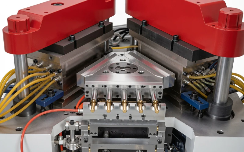
Figure 2: A multi-cavity IBM mold. The combined surface area of every cavity, multiplied by the injection pressure, equals the total force attempting to blow the mold open.
3. The “Tonnage Class” Illusion: Marketing vs. Mechanical Reality
If calculating clamping force is a matter of strict physics, why is there so much confusion in the market? The problem lies in how machine manufacturers classify and market their equipment.
“Tonnage Class” is often a rounded, legacy designation rather than a precise engineering metric. Furthermore, the way tonnage is measured varies globally:
- US Short Tons: Historically used by North American brands (e.g., Jomar, Uniloy). One US Ton equals 2,000 lbs of force (approx. 8.89 kN).
- Metric Tons: Used by European and Asian manufacturers (e.g., ZQ Series, SUMA). One Metric Ton equals 1,000 kg of force (approx. 9.81 kN).
Because of this discrepancy, a legacy American “85-Ton” machine might generate approximately 756 kN of force, while a modern European-spec “80-Ton” machine generates a full 800 kN. The machine with the “smaller” class number on the badge actually applies more clamping force to the mold.
Static vs. Dynamic Clamping Force
Another critical distinction is how the machine achieves its tonnage. Many budget machines use toggle-linkage mechanisms. While a toggle might hit its rated “peak” tonnage at the exact moment of lock-up (static force), that force can drop slightly as the mechanical linkages flex under the immense dynamic pressure of injection. High-end platforms, such as the ZQ Series, utilize direct-acting hydraulic or servo-hydraulic rams that maintain constant, unyielding pressure (dynamic force) throughout the entire injection and packing phase, ensuring absolute stability.
4. The Catastrophic Consequences of Insufficient Clamping Force
What happens when your machine is undersized for the tooling? When the Separation Force exceeds the Clamping Force by even a fraction of a percent, the mold halves separate—a phenomenon known as “mold blowing.” The results are detrimental to both part quality and machine lifespan.
1. Parting-Line Flash & Cleanroom Contamination
As the mold opens infinitesimally, molten plastic escapes the cavity boundary. This creates a razor-thin webbing of plastic (flash) along the preform’s parting line and neck threads. In a GMP pharmaceutical cleanroom, this flash breaks off during handling, creating airborne micro-particulates and dust, leading directly to lot failures.
2. Core Rod Deflection & Wall Thinning
If the mold is not clamped tightly, the internal injection pressures can shift the precision core rods off-center. When the core rod is no longer perfectly concentric with the cavity, the resulting preform will have uneven wall thickness. Once blown, the bottle will feature a thin, weak side prone to bursting or failing drop-tests.
3. Premature Tooling Degradation
High-quality IBM molds are million-cycle, precision-hardened assets. When a mold repeatedly flashes, a microscopic layer of plastic cures on the parting line. On the next cycle, the machine clamps down onto this hardened plastic, crushing the delicate cavity edges. Over time, the steel is permanently deformed (coining), and the mold is ruined.
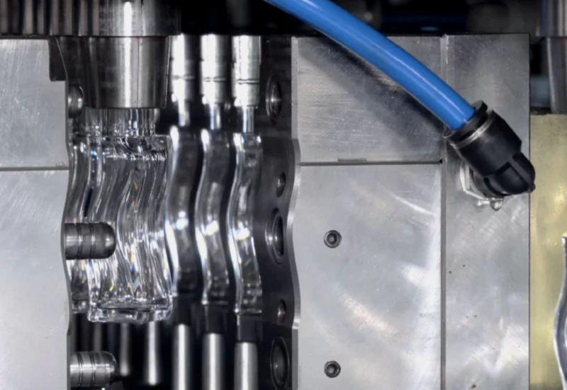
Figure 3: Precision IBM neck rings and cavities. Insufficient clamping force allows plastic to escape between these steel plates, causing permanent “coining” damage to the tool.
5. Platen Deflection: Why Force Distribution Matters
It is entirely possible to have a machine mathematically rated for 1,350 kN (135T) that still flashes a mold requiring only 1,000 kN. How? The answer lies in Platen Deflection.
The clamping force is transferred from the hydraulic cylinders, through the massive steel platens, and into the mold. However, steel is not infinitely rigid; it acts like a very stiff spring. If a mold is extremely wide (like a 24-cavity landscape layout), the pressure in the center of the mold pushes back against the center of the platen.
If the machine’s platen is too thin or poorly engineered, it will “bow” or deflect in the center. The edges of the mold will be clamped tightly by the tie-bars, but the center cavities will separate by a few hundredths of a millimeter—just enough to flash. This is why top-tier machines prioritize massive, heavily ribbed cast-iron platens. The ZQ Series, for example, utilizes finite element analysis (FEA) to engineer platens that guarantee less than 0.05 mm of deflection under maximum load, ensuring uniform force distribution across every single cavity.
6. The Secondary Clamp: The Blow Station and Utility Planning
While the Injection Station receives the vast majority of engineering focus, the IBM process features a second clamping unit that is equally critical: the Blow Station Clamp.
At Station 2, the hot preforms are inflated to their final shape. To do this, high-pressure compressed air (typically 0.8 to 1.2 MPa) is blasted into the core rods. Just like the injection polymer, this air creates internal pressure that attempts to blow the secondary mold open. Therefore, the blow station features its own dedicated clamping mechanism (usually rated between 60 kN to 180 kN depending on machine size).
Because this station relies entirely on massive volumes of pneumatic force to expand the parisons, the external utility infrastructure supplying the machine is an active participant in the clamping and forming process. If the factory air supply fluctuates in pressure, the parisons will not expand fully into the mold corners, resulting in rejected bottles with heavy bottoms and thin shoulders.
⚙ The Cleanroom Utility Mandate: Class 0 Air
In pharmaceutical IBM production, the blow air comes into direct contact with the internal sterile environment of the vial. Any oil aerosol introduced by a standard lubricated air compressor will coat the bottle interior, failing GMP standards immediately.
To guarantee stable blowing pressure and absolute sterility, a dedicated ISO 8573-1 Class 0 system is mandatory. Integrating a purpose-built system like the CM-B Series Oil-Free Screw Air Compressor ensures that your blow station receives the sustained, high-volume, uncontaminated pneumatic flow required to combat blow-station separation forces and form flawless containers.
7. Troubleshooting Guide: Is It Clamp Force, Pressure, or Temperature?
If your IBM line suddenly begins producing flashed bottles, operators often instinctively increase the machine’s clamping force (if the system allows it). However, flashing is not always a tonnage failure. Before pushing your machine to its absolute structural limits, engineers should evaluate the “Process Triangle”:

Figure 4: A perfectly executed IBM container. When clamping force is calculated correctly against the projected area, the result is a seamless, flash-free pharmaceutical vial.
8. How to Specify the Right Machine: The Procurement Checklist
Never purchase a machine based on a general “class” recommendation. Follow this definitive engineering checklist to verify your requirements:
- Demand the 2D CAD Drawings: Ask your toolmaker for the exact projected surface area ($cm^2$) of the mold layout, including the runner system.
- Identify Peak Injection Pressure: Consult your resin supplier’s data sheet for the required packing pressure. If processing a viscous material like Polycarbonate or PCTG, expect pressures 20-30% higher than standard HDPE.
- Calculate the Mathematical Minimum: Use the formula ($Area \times Pressure \times 1.25$) to find your required kN.
- Verify True Machine Output: Check the machine’s spec sheet for Continuous Hydraulic Clamping Force in kN. Disregard the marketing “Ton” badge.
- Check the Platen Layout: Ensure the mold base dimensions physically fit within the tie-bar spacing of the chosen machine, prioritizing landscape orientations (like the ZQ Series) for superior thermal balancing.
Conclusion: Sizing for Operational Excellence
Understanding injection blow molding clamping force is the difference between running a highly profitable, automated cleanroom cell and a maintenance nightmare plagued by constant tool repair and scrap generation. Tonnage class is merely a label; clamping force is the physical law governing your production floor. By calculating your exact projected area requirements and demanding robust platen architectures, you safeguard your capital investment.
Need Assistance Calculating Your Machine Requirements?
Our engineering team is ready to review your bottle CAD files and cavity targets. We will mathematically calculate your required clamping force, shot weight, and air utility needs to recommend the perfect, highly efficient platform for your facility.