
Every second of ISBM cycle time has a direct cost: at 3,600 bottles per hour on a 4-cavity machine, one additional second of cooling adds roughly 600 fewer bottles per shift. Yet most discussions of cycle time optimisation focus on injection parameters, blow timing and stretch rod speed — the process variables that operators control through the PLC. The variable that has the largest single influence on achievable cycle time is not a parameter setting. It is the physical design of the cooling channels inside the mold. How far the channels run from the cavity surface, how fast the coolant flows, what temperature it reaches at the mold exit, and what steel the mold is made from — these are tooling decisions made at design time that determine whether a given cycle time is physically achievable, regardless of how well the machine is set up. This guide provides the engineering framework for understanding and specifying ISBM mold cooling system design, with quantified data on how each design variable affects cycle time and wall thickness uniformity.
1. Why Mold Cooling Is the Primary Cycle Time Constraint
In a typical ISBM cycle, the four phases — injection, conditioning, stretch blow and ejection — share the total cycle time. Of these, injection, blow and ejection are mechanically constrained: they take as long as the resin flow, orientation mechanics and mechanical movements require, and shortening them beyond their physical minimums produces defects. The cooling time embedded within the injection and blow phases is different: it is determined by how fast the mold can remove heat from the polymer, and this is a function of the mold design — not the machine parameters.
In a well-designed ISBM mold running PETG at a 5.5-second cycle time, cooling time accounts for approximately 55 to 65 percent of the total cycle. On a poorly cooled mold running the same resin and bottle geometry on the same machine, cooling time may account for 75 to 80 percent of cycle, forcing the total up to 7.5 to 8.5 seconds — a 40 to 55 percent cycle time penalty that no process parameter change can overcome.
The cooling time limit: The minimum achievable cooling time for a given polymer, wall thickness and mold temperature is set by the thermal diffusivity of the polymer and the thermal conductivity of the mold steel. No process adjustment can reduce cooling time below the value defined by these material properties. The only way to reduce minimum cooling time is to change the mold design: move channels closer to the cavity surface, increase coolant flow velocity into the turbulent regime, or use higher-conductivity mold steel.
2. The Physics of Mold Heat Transfer
Heat flows from the hot polymer through the mold wall to the cooling water in a three-stage process. Understanding which stage is the limiting step determines where design effort should be focused.
-
1Polymer to mold wall (conduction)Heat conducts from the hot polymer melt through the thin solidified polymer skin and into the mold steel surface. This stage is governed by the thermal diffusivity of the polymer and the contact conductance at the polymer-mold interface. For PETG, thermal diffusivity is approximately 0.85 × 10⁻⁷ m²/s — lower than PET (1.1 × 10⁻⁷) and significantly lower than most mold steels. This is why PETG requires longer cooling times than PET at the same wall thickness.
-
2Through the mold wall (conduction)Heat conducts from the cavity surface through the mold steel to the cooling channel wall. This stage is governed by the thermal conductivity of the mold steel and the distance from the cavity surface to the channel wall. This is the stage most directly controlled by mold design — channel placement is the primary variable. For a given steel type, halving the distance from cavity surface to channel wall approximately doubles the heat flux at that point.
-
3Channel wall to coolant (convection)Heat transfers from the channel wall into the flowing coolant by convection. This stage is governed by the convective heat transfer coefficient, which depends almost entirely on whether the coolant flow is laminar or turbulent. Turbulent flow (Reynolds number above 4,000) produces heat transfer coefficients 5 to 8 times higher than laminar flow. This is the stage most commonly under-designed — flow rates that look adequate on paper often produce laminar flow in standard 8mm channels.
Re = (v × D × ρ) ÷ μ
v = coolant velocity (m/s) | D = channel diameter (m) | ρ = coolant density (kg/m³) | μ = dynamic viscosity (Pa·s)
For water at 12°C in an 8mm channel: Re > 4,000 requires flow velocity above approximately 0.53 m/s (flow rate 16 l/min). Most ISBM molds receive 8 to 12 l/min per circuit — often in the laminar-to-transitional range that provides only a fraction of the maximum achievable convective heat transfer.
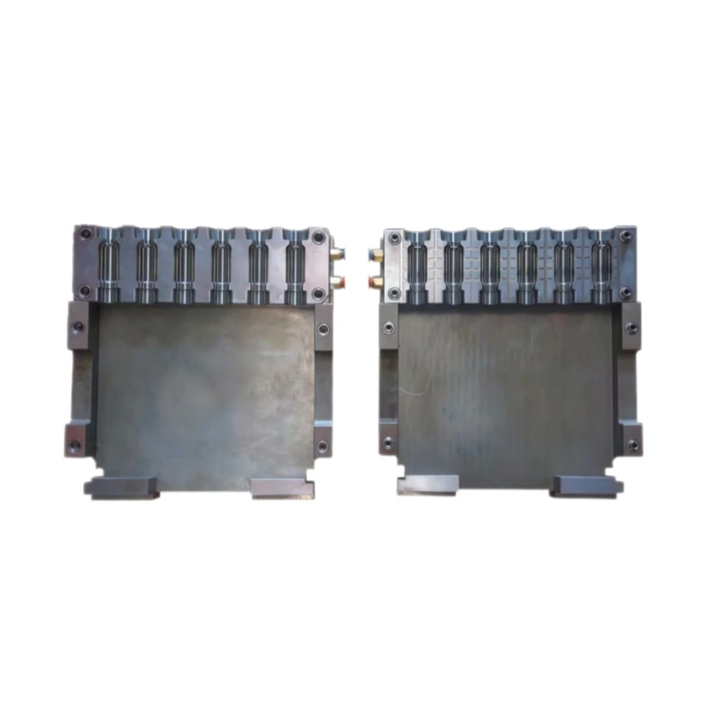
Fig. 1 — ISBM preform mold (left) and blow mold (right) set. The cooling channel network inside each mold block is invisible once assembled but determines the minimum achievable cycle time and the uniformity of wall thickness in the finished bottle. These are permanent design decisions made before the mold is cut.
3. Channel Geometry: Diameter, Depth and Spacing
Channel geometry is the primary controllable variable in mold cooling design. Three dimensions define the geometry of each cooling circuit: channel diameter, the distance from the channel centreline to the cavity surface (channel depth), and the centre-to-centre spacing between adjacent channels.
3.1 Channel Diameter
Larger diameter channels carry more coolant volume but at lower velocity for the same inlet pressure. This creates a counter-intuitive design tension: a 10mm channel at 10 l/min has lower coolant velocity than an 8mm channel at 10 l/min, meaning the 10mm channel may actually produce less efficient heat transfer despite carrying more water. For ISBM molds, the optimal channel diameter range for preform cavities is 6 to 10mm:
- ▶6mm channels: Highest velocity at a given flow rate; most efficient convective heat transfer; more drilling operations required to achieve equivalent coverage. Used for small cavities (under 30mm cavity diameter) and near-surface channels within 8mm of the cavity wall.
- ▶8mm channels: The standard for most ISBM preform mold cores and cavities. Balances velocity (turbulent at 12–16 l/min) with fabrication practicality. Most HGY series machine cooling circuits are designed for 8mm channel connections.
- ▶10mm channels: Used for blow mold bodies and larger preform cavity blocks. Lower velocity risk requires higher inlet flow rates (18–24 l/min) to maintain turbulent regime. Appropriate for large cavities where channel coverage must extend over a wider area.
3.2 Channel Depth (Distance from Cavity Surface)
The distance from the channel centreline to the nearest cavity surface is the most sensitive geometry parameter. Industry practice establishes the following relationship between depth and channel diameter as the design guideline:
Recommended Channel Depth Rule
Depth = 1.0 to 1.5 × Channel Diameter
For an 8mm channel: target depth 8–12mm from cavity surface centreline
For PETG thick-wall applications: use lower end of range (1.0×D) to maximise heat extraction
Channels deeper than 2×D (more than 16mm from the cavity surface for an 8mm channel) are in the poor-cooling zone — the steel conducts heat slowly enough at this distance that the cooling water temperature, flow rate and even steel type have diminishing influence on the cavity surface cooling rate. Channels shallower than 0.75×D risk mold stress cracking from thermal fatigue at the thin wall between the channel and the cavity surface.
3.3 Channel Spacing (Pitch)
Centre-to-centre spacing between adjacent parallel channels determines the uniformity of the temperature field at the cavity surface. Channels that are too widely spaced produce a “scalloped” temperature profile — cool zones directly above channels, warm zones between them. The temperature variation this creates translates directly into wall thickness variation in the finished bottle. Recommended pitch for ISBM preform molds: 2.5 to 3.5 times the channel diameter. For 8mm channels, this means channels spaced 20 to 28mm apart centre-to-centre.
4. Flow Velocity and Turbulence: Why Pressure Matters More Than Volume
The most common cooling system underperformance found during ISBM mold audits is not insufficient water volume — it is insufficient flow velocity. Production teams measure the total water volume supplied to the mold circuit (litres per minute) and assume more is better. The correct metric is coolant velocity inside the channel, which determines whether the flow is turbulent and therefore whether the convective heat transfer coefficient is in the efficient range.
| Flow Rate (8mm channel) | Velocity (m/s) | Reynolds Number | Flow Regime | Relative Heat Transfer |
|---|---|---|---|---|
| 5 l/min | 0.17 m/s | 1,360 | Laminar | Baseline (1.0×) |
| 8 l/min | 0.27 m/s | 2,170 | Transitional | 1.8 – 2.5× |
| 12 l/min | 0.40 m/s | 3,200 | Transitional | 2.5 – 4.0× |
| 16 l/min | 0.53 m/s | 4,240 | Turbulent | 5.0 – 6.5× |
| 24 l/min | 0.80 m/s | 6,400 | Turbulent | 7.0 – 8.5× |
Water at 12°C, 8mm channel diameter. Reynolds numbers calculated using ρ = 999 kg/m³, μ = 1.23 × 10⁻³ Pa·s.
Practical implication: Increasing coolant flow from 8 l/min to 16 l/min in an 8mm channel — a doubling of flow rate — can increase the convective heat transfer coefficient by a factor of 2 to 3. This directly reduces the time required to cool the preform or bottle to ejection temperature, typically translating to a reduction in cooling time of 0.5 to 1.5 seconds. For a mold with adequate channel placement, increasing supply pressure to the mold is often the cheapest cycle time reduction available.
5. Zone Layout: Preform Mold, Blow Mold and Neck Ring Circuits
An ISBM mold set contains three thermally distinct circuit zones, each with a different cooling objective and therefore different design requirements:
Preform Cavity and Core
Objective: Solidify preform outer skin and freeze neck geometry completely. Retain internal heat in the preform body for blow station.
Target temp: 8 – 15°C at cavity; 10 – 18°C at core
Design priority: Channel proximity to core pin surface; differential cooling between core (cooler) and cavity (slightly warmer) to promote skin solidification without over-cooling the preform body
Neck Ring Circuit
Objective: Freeze neck thread geometry completely before turntable rotation. This is the most time-critical circuit in the preform mold.
Target temp: 5 – 12°C (coldest circuit in the mold)
Design priority: Maximum channel proximity; dedicated chilled water supply independent of the preform cavity circuit; flow rate sufficient for turbulent regime even at low temperature
Blow Mold Circuit
Objective: Cool the blown bottle body below the distortion temperature before ejection. Longer cooling time is acceptable here as the blow station time is typically longer.
Target temp: 10 – 20°C
Design priority: Uniform temperature across all cavity surfaces; symmetric channel layout to prevent body distortion; adequate cooling at the base where the PET/PETG gate zone is thickest
On a 4-station HGY150-V4 or HGY150-V4-EV machine, the conditioning station (Station 2) actively manages preform temperature between the injection and blow stations. This reduces the dependency on the injection mold cooling circuit to achieve the correct preform temperature at the blow station — the conditioning station can compensate for a modest over-cooling at injection. On 3-station machines, the injection mold cooling circuit must achieve exactly the right preform temperature in a single step, making the design tolerance significantly tighter and the consequences of cooling circuit deficiency more severe.
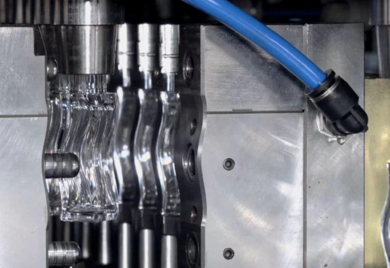
Fig. 2 — ISBM mold assembly with three independent cooling circuit zones: the neck ring circuit (coldest, target 5–12°C) surrounds the thread-forming surface; the core pin circuit controls preform inner surface temperature; the cavity circuit controls the outer surface. Each circuit must be independently controllable — shared circuits cannot be optimised for the different temperature targets each zone requires.
6. Mold Steel Selection: How Thermal Conductivity Affects Cooling Rate
Mold steel selection directly affects Stage 2 of the heat transfer chain — conduction through the mold wall. Higher-conductivity steels allow the same heat flux with either more channel depth (simpler machining) or less cooling time (faster cycles) at the same channel depth.
4Cr13 Stainless Steel
Standard ISBM mold material
- Thermal conductivity: 25 – 28 W/m·K
- Hardness after heat treatment: HRC 48 – 52
- Corrosion resistance: Good — suitable for chilled water circuits down to 5°C without condensation risk on mold exterior
- Application: Standard PETG and PET cosmetic and pharmaceutical ISBM molds. Good balance of cooling performance, corrosion resistance and polishability for optical clarity requirements.
- Typical mold life: 3 – 5 million cycles for standard PETG applications
S136 / STAVAX ESR
Premium imported stainless tool steel
- Thermal conductivity: 24 – 27 W/m·K
- Hardness after heat treatment: HRC 50 – 54
- Corrosion resistance: Excellent — higher chromium content than 4Cr13; resists pitting in aggressive coolant environments
- Application: Premium cosmetics requiring mirror-polish surface finish (Ra < 0.025μm); pharmaceutical applications with aggressive chemical resistance requirements; corrosive resin processing (PC, some specialty grades).
- Typical mold life: 5 – 8 million cycles; higher hardness resists nick marks from core rod contact
Beryllium Copper (BeCu)
High-conductivity insert material
- Thermal conductivity: 105 – 130 W/m·K (4 – 5× higher than steel)
- Hardness: HRC 38 – 42 (after age hardening)
- Application: Core pin inserts in thick-wall preform molds; blow mold base inserts where gate zone is slowest to cool; areas where channel placement is geometrically difficult. Not used for full mold bodies — used as targeted inserts where localised cooling enhancement is required.
- Cycle time benefit: 15 – 35% cooling time reduction at the insert zone vs equivalent steel geometry
P20 / 718 Pre-hardened Steel
Low-volume tooling (not recommended for ISBM)
- Thermal conductivity: 29 – 33 W/m·K
- Hardness: HRC 28 – 34 (pre-hardened, no heat treatment required)
- Limitation: Insufficient corrosion resistance for chilled-water ISBM circuits below 15°C — rusts internally, restricts coolant flow and degrades cooling performance progressively. Lower hardness means early surface wear on neck ring contact surfaces.
- Verdict: Appropriate for prototype or sampling molds only. Not recommended for production ISBM molds with chilled water cooling.
7. Cooling Uniformity and Wall Thickness Consistency
Non-uniform cooling at the preform stage is the most common tooling-related cause of wall thickness variation in ISBM bottles. The mechanism is straightforward: a preform that reaches the blow station with an uneven temperature profile — hotter on one side than the other — will stretch unevenly. The hotter zone is softer and stretches further; the cooler zone is stiffer and resists stretch. The result is a bottle with asymmetric wall thickness that passes visual inspection but fails drop tests, top-load tests or fill accuracy requirements.
Three cooling circuit design problems cause temperature non-uniformity in the preform:
- ▶Asymmetric channel layout: Channels on one side of a multi-cavity core but not the other. Common in tooling where channel drilling conflicts with ejector pin positions or support structures. Results in a consistent left-right or front-back wall thickness bias across all bottles from that cavity.
- ▶Series-connected circuits (daisy-chaining): Multiple cavities connected in series so the coolant passes through cavity 1, then cavity 2, then cavity 3 sequentially. The coolant warms progressively along the chain — cavity 1 receives 12°C water and cavity 4 might receive 18°C water. This produces systematic gram weight and wall thickness variation between cavities that cannot be corrected by process parameters.
- ▶Inadequate gate zone cooling: The preform base, where the gate is located, is the thickest zone and the last to solidify. If the cooling channel network does not extend to within 10mm of the gate zone, this area remains hot at ejection — producing a thick, partially crystallised base that appears as base haze in PETG bottles and as a heavy base in finished bottle weight measurement.
For premium cosmetic and pharmaceutical ISBM bottles, the maximum acceptable preform surface temperature variation at the blow station entry is ±5°C across any cross-section of the preform body. Above this variation, wall thickness non-uniformity typically exceeds the ±15% limit used in premium packaging specifications. Achieving this requires: parallel-connected circuits (not series), symmetric channel layout, turbulent flow confirmed by Reynolds number calculation, and mold temperature monitoring at the coolant outlet of each circuit.
8. Quantified Impact: How Much Cycle Time Each Design Variable Controls
The following table summarises the measured cycle time impact of each cooling design variable for a reference case: 4-cavity preform mold, 30ml PETG cosmetic bottle, 6g preform, 8mm channels in 4Cr13 steel, baseline cycle time 6.8 seconds.
| Design Change | Baseline | Improved | Cycle Time Saving | Annual BPH Gain (4-cav) |
|---|---|---|---|---|
| Flow rate (laminar to turbulent) | 8 l/min (Re 2,170) | 18 l/min (Re 4,860) | 0.6 – 1.0 s | +390,000 – 660,000 |
| Channel depth (deep to near-surface) | 18mm from surface | 10mm from surface | 0.4 – 0.8 s | +260,000 – 530,000 |
| Coolant temperature (warmer to colder) | 18°C | 10°C | 0.3 – 0.6 s | +200,000 – 400,000 |
| Gate zone channel added (missing to present) | No gate zone cooling | Channel within 10mm | 0.2 – 0.5 s | +130,000 – 330,000 |
| BeCu insert at core pin base | 4Cr13 throughout | BeCu insert at base 30mm | 0.3 – 0.7 s | +200,000 – 460,000 |
Reference: 4-cavity mold, 6,000 production hours per year at 4-cavity output. Annual BPH gain = cycle time saving ÷ new cycle time × 3,600 × 4 × 6,000. These are indicative ranges based on engineering calculation and field measurement data.
9. Cooling System Audit: What to Measure on Your Existing Mold
For operators with existing ISBM molds experiencing unexpectedly long cycle times or wall thickness variation, a cooling system audit using the following protocol identifies the root cause without dismantling the mold.
-
1Measure coolant inlet and outlet temperature per circuitInstall digital thermometers at the inlet and outlet of each independent circuit. Record temperatures during steady-state production. Target: outlet temperature no more than 3°C above inlet for the preform cavity circuit; no more than 5°C for the blow mold circuit. Higher temperature rise indicates either insufficient flow rate or the circuit is cooling too large a volume of steel in series — split the circuit.
-
2Calculate Reynolds number for each circuitMeasure flow rate (l/min) and channel diameter (from mold drawing). Calculate velocity: v = flow rate (l/s) ÷ channel cross-section area (m²). Calculate Re using water properties at the operating temperature. If Re is below 4,000, increase supply pressure or install a dedicated pump — coolant flow from the chiller is often at inadequate pressure for the mold circuit resistance.
-
3Infrared thermography of the mold cavity surfaceUsing an infrared camera, photograph the cavity face immediately after a production cycle (machine opened, before preform is ejected). Hot spots visible on the cavity surface indicate zones where the cooling channel network does not extend. These zones correspond directly to bottle locations that are last to cool and most likely to show wall thickness non-uniformity or, in PETG, base haze.
-
4Gram weight and wall thickness mapping across cavitiesWeigh 20 consecutive bottles from each cavity. Map gram weight variation in the order they were produced. A systematic cavity-to-cavity pattern (cavity 1 consistently heavier than cavity 4) confirms series cooling — the coolant exits cavity 1 warmer and enters cavity 4 at a higher temperature. A random pattern suggests random process variation, not a structural cooling design problem.
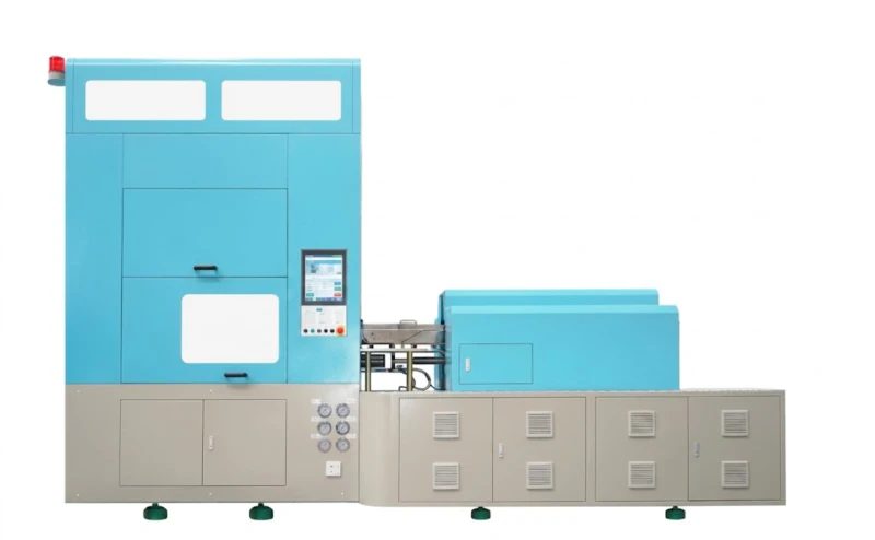
Fig. 3 — The HGY150-V4-EV with mold temperature controller (MTC, lower right). The MTC manages preform mold and blow mold cooling water temperature independently, maintaining setpoints against production heat load variation. The machine instrumentation provides coolant inlet temperature data; independent outlet monitoring and flow measurement provide the additional data needed for a complete cooling audit.
10. Worked Example: Cycle Time Improvement on a 30ml PETG Cosmetic Mold
A packaging manufacturer running a 4-cavity 30ml PETG serum bottle mold on an HGY150-V4-EV was achieving a 7.2-second cycle time with 18% wall thickness variation between the thinnest and thickest body zone — above their 15% acceptance limit. A cooling audit identified three problems:
-
1Finding: Laminar coolant flowFlow rate was 9 l/min in 8mm channels. Re = 2,430 — transitional, below turbulent threshold. Outlet temperature 4.8°C above inlet. Action: Installed a dedicated mold pump raising supply pressure from 0.25 MPa to 0.45 MPa, increasing flow to 17 l/min (Re = 4,590, turbulent). Cycle time reduction: 0.8 seconds.
-
2Finding: Series-connected cavity circuitsAll 4 cavities were connected in series. Outlet temperature from cavity 4 was 6.2°C warmer than inlet — cavity 4 cavities were running at a systematically higher temperature. Gram weight from cavity 4 was consistently 0.4g heavier. Action: Mold reworked to parallel circuits (4 independent inlets and outlets from a single manifold). After rework, cavity-to-cavity gram weight variation reduced from 0.4g to 0.06g. Wall thickness variation improved from 18% to 11%.
-
3Finding: Insufficient neck ring coolingNeck ring circuit was supplied from the same circuit as the preform cavity — receiving 14°C water (4°C above chiller setpoint due to shared series connection). Action: Dedicated neck ring circuit connected directly to chiller supply, receiving 10°C water at 14 l/min independently. Cycle time reduction at blow station (due to faster neck freeze): 0.4 seconds.
Cycle time: 7.2s → 6.0s (16.7% reduction). Annual additional output at 4 cavities: +1,200,000 bottles/year. Wall thickness variation: 18% → 11% (within the 15% limit). All improvements achieved from circuit rework and pump installation — no new mold steel, no machine upgrade.
A stable, matched air supply — specifically a correctly sized oil-free air compressor for ISBM — was also confirmed during the audit: blow pressure stability at ±0.05 MPa throughout the run, confirming that the wall thickness variation was attributable entirely to cooling non-uniformity rather than blow process variation.
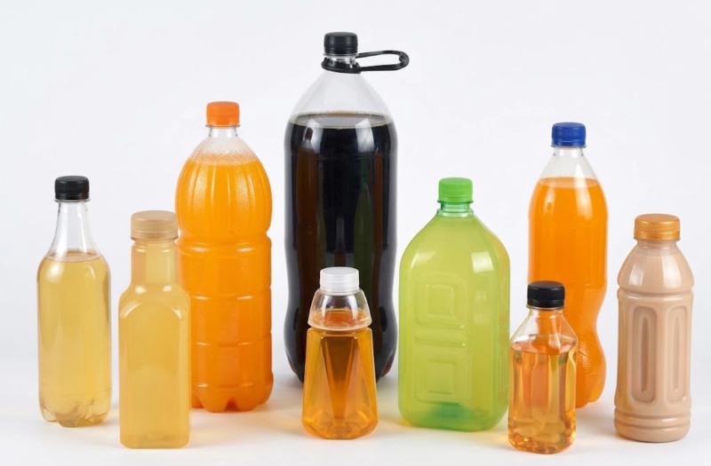
Fig. 4 — PETG cosmetic bottle samples post cooling-system improvement: wall thickness variation at 11% (within the ±15% premium packaging limit), cycle time 6.0 seconds, zero wall collapse on drop test. The cooling circuit redesign — no new mold, no new machine — produced the output improvement equivalent to adding a fifth cavity on the original slower cycle.
1. Turbulent flow is not optional. Verify Reynolds number for every circuit. Laminar flow in cooling channels reduces heat transfer by a factor of 5 to 8. Increasing supply pressure is the cheapest cycle time intervention available.
2. Channel depth determines the cooling floor. Channels deeper than 2×D from the cavity surface produce diminishing returns regardless of flow rate or steel type. Mold rework to move channels closer to the cavity surface is often the only way to break through a cycle time plateau.
3. Parallel circuits eliminate systematic cavity-to-cavity variation. Series-connected circuits produce systematic temperature gradients between cavities that process parameters cannot correct. Parallel circuits are not more expensive to machine — they require additional manifold connections but no additional drilling.
4. The neck ring circuit must be independent. A neck ring circuit sharing water with the preform cavity circuit will always be warmer than optimal. The neck is the most dimensionally critical feature of the bottle — its cooling circuit deserves its own supply line.
5. Steel conductivity matters less than channel placement and flow regime. Upgrading from 4Cr13 to S136 at the same channel depth and flow rate delivers less cycle time improvement than moving channels 6mm closer to the cavity surface at the same flow rate. Get the geometry right before spending on premium steel.
Need a Cooling Channel Audit for Your ISBM Mold?
Share your mold drawings, coolant circuit data and current cycle time with our engineers. We will identify the limiting step in your cooling system and provide specific channel geometry and flow rate recommendations — typically within 48 hours.