Output is the number that justifies every ISBM machine investment. Yet it is also one of the most misquoted specifications in the industry — because manufacturers publish theoretical maximum figures based on the fastest possible cycle time, the fewest cavities and the lightest possible bottle. Real-world output is almost always lower, and understanding why requires a clear engineering framework. This guide breaks down the ISBM output calculation into its component parts: what drives cycle time, how cavity count multiplies production rate, how to apply the formulas to your specific bottle, and where the gaps between datasheet and shop floor typically appear.
1. Why Output Calculation Matters Before You Buy
The single most common mistake in ISBM machine procurement is accepting the manufacturer’s published theoretical output as a planning figure. A machine rated at “4,000 bottles per hour” on the specification sheet may deliver 2,400 to 2,800 bottles per hour under real production conditions, depending on bottle geometry, resin type, cavity count and operator efficiency. The difference between these figures — 30 to 40% — represents the gap between a profitable line and one that fails to meet its production targets.
Understanding how to calculate output from first principles allows you to:
- ✓Verify whether a given machine size can meet your annual volume target before purchase
- ✓Select the right cavity count for your bottle size and weight combination
- ✓Identify which part of the cycle is the bottleneck — and whether it can be reduced
- ✓Set realistic shift targets and OEE benchmarks for your production planning team
- ✓Size auxiliary equipment — particularly air compressors and chillers — correctly for the actual peak demand
The core principle: ISBM output is determined by two independent variables — cycle time and cavity count. Improving either one increases output proportionally. Understanding them separately is the key to systematic output optimisation.
2. Cycle Time: The Four Stages and What Controls Each
In a one-step ISBM machine, the cycle time is the elapsed time between one ejection event and the next — the time it takes to complete one full rotation of the turntable. Because the four stations operate simultaneously (injection, conditioning, stretch blow, ejection are all happening in parallel), the cycle time is not the sum of all four stage times. It is determined by the slowest station — whichever station takes longest controls the overall throughput.
2.1 Station 1 — Injection Time
Injection time comprises four sub-phases: fill time (melt flowing into the cavity), pack/hold time (compensating shrinkage), gate freeze time (solidification of the gate vestige) and decompression time (screw suck-back). For standard cosmetic and pharmaceutical preforms of 5–30g, typical injection time ranges from 3.5 to 7.0 seconds. Heavier preforms (50–130g) for wide-mouth or thick-walled bottles extend this to 8–14 seconds.
Injection time is controlled by: preform weight (more material = longer fill), resin viscosity (higher molecular weight resins are slower), injection pressure and speed settings, and the number of barrel heating zones. It is the most difficult station time to reduce without compromising preform quality.
2.2 Station 2 — Conditioning Time (4-Station Machines)
On a 4-station machine, the conditioning station holds the preform while its internal temperature equalises after injection. For standard thin-walled preforms, conditioning time is typically 1.5 to 3.0 seconds — short enough that it is rarely the bottleneck. For thick-walled preforms (wall > 4mm), conditioning can extend to 5–8 seconds and may become the limiting station. On 3-station machines, there is no separate conditioning station — the preform moves directly from injection to blow, which restricts the range of bottle geometries the machine can handle effectively.
2.3 Station 3 — Stretch Blow Time
Stretch blow time includes: mould close time, stretch rod extension, low-pressure pre-blow, high-pressure main blow, pressure hold (cooling under pressure), pressure exhaust and mould open. For standard bottles, this runs from 2.5 to 5.0 seconds. The dominant variable is cooling time — the time the bottle must remain under blow pressure while it cools below its ejection temperature. This is controlled by mould temperature (cooled by chilled water), wall thickness and resin thermal properties.
2.4 Station 4 — Ejection and Turntable Index Time
Ejection time is typically the shortest station — the finished bottle is mechanically stripped from the core rod, conveyed away, and the turntable indexes to the next position. On servo-driven machines (EV series), indexing is faster and more precise than on hydraulic machines. Ejection typically takes 1.0 to 2.0 seconds and is rarely the bottleneck unless the take-out mechanism is misadjusted or the conveyor is backed up.
Because all four stations run in parallel, reducing a non-limiting station’s time has zero effect on output. If injection takes 6s and blow takes 4s, reducing blow to 3s gains nothing. The only productive optimisation target is the current limiting station — almost always injection for preforms above 20g, and blow cooling for very thin-walled bottles below 10g.
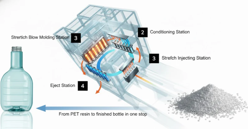
Fig. 1 — In the 4-station ISBM cycle, all four stations operate in parallel. Cycle time equals the duration of the slowest station — not the sum of all four. This parallel architecture is the fundamental reason one-step ISBM achieves higher output efficiency than sequential processes.
3. The Output Formula: Bottles Per Hour
The fundamental ISBM output formula is straightforward:
Core Output Formula
BPH = (3,600 / CT) × N
BPH = Bottles Per Hour | CT = Cycle Time in seconds | N = Number of cavities
This gives theoretical maximum output under continuous, uninterrupted production. To arrive at practical output, apply an efficiency factor (discussed in Section 6):
Practical Output Formula
Actual BPH = BPH × OEE
OEE = Overall Equipment Effectiveness (typically 0.75 – 0.88 for ISBM lines)
3.1 Formula Applied — Three Examples
| Scenario | Cycle Time | Cavities | Theoretical BPH | Practical BPH (OEE 0.82) |
|---|---|---|---|---|
| 30ml cosmetic serum (PETG, 6g) | 5.0 s | 6 | 4,320 | 3,542 |
| 100ml pharmaceutical syrup (PP, 18g) | 8.5 s | 4 | 1,694 | 1,389 |
| 500ml premium water bottle (PET, 22g) | 7.2 s | 2 | 1,000 | 820 |
3.2 Annual Volume Formula
To convert hourly output to annual production capacity, apply the planned operating schedule:
Annual Volume Formula
Annual = Actual BPH × Hours/Day × Days/Year
Example: 3,542 BPH × 20 h/day × 300 days = 21.25 million bottles/year
4. Cavity Count: Multiplying Output Without Changing Cycle Time
Adding a cavity doubles that cavity’s share of output without adding any time to the cycle. A 2-cavity mould running at 7s produces 1,028 bottles per hour; a 4-cavity mould on the same machine at the same cycle time produces 2,057 BPH — exactly double. This makes cavity count the most powerful lever for increasing output on an existing machine, and cavity selection the most important tooling decision in the ISBM investment.
4.1 What Limits Maximum Cavity Count
Four constraints set the practical upper limit on cavity count for any given machine and bottle combination:
-
1Injection clamping force vs total projected areaEach additional cavity adds projected area at the parting plane. The total injection clamping force must exceed total cavity pressure multiplied by total projected area. Exceed this limit and the mould opens under injection pressure, producing flash at every cycle. For the HGY150-V4 at 150KN injection clamping, this typically limits cavities to 4–8 for standard neck diameters.
-
2Total preform weight vs injection capacityAll cavities are filled from a single shot. N cavities times preform weight must not exceed the machine’s theoretical injection volume. At 90% shot utilisation (the practical limit to avoid over-packing), a HGY150-V4 with 310g theoretical capacity supports a maximum of 10 cavities at 28g per preform, or 6 cavities at 45g.
-
3Blow clamping force vs total bottle projected areaThe blow mould must clamp against the 2.0–3.5 MPa blow pressure acting on the total plan area of all bottles in the mould. More cavities means more projected area and greater opening force. The HGY150-V4 blow clamping of 200KN (single side) typically supports up to 8 cavities for a 40mm diameter bottle body.
-
4Mould platen size vs total mould footprintThe preform injection mould and blow mould must both physically fit within the machine’s platen dimensions. For the HGY150-V4, the maximum mould platen is 4,200 x 1,400mm. Bottle diameter and cavity pitch set the minimum mould width per cavity; beyond a certain count, the mould simply exceeds the platen envelope.
4.2 Cavity Count by Bottle Volume — Reference Guide
| Bottle Volume | Typical Preform Weight | HGY50-V3-EV (max) | HGY150-V4 (max) | HGYS280-V6 (max) |
|---|---|---|---|---|
| 10 – 30 ml | 3 – 8 g | 4 – 6 | 6 – 10 | 12 – 16 |
| 50 – 100 ml | 10 – 22 g | 2 – 4 | 4 – 8 | 8 – 12 |
| 150 – 300 ml | 22 – 45 g | 1 – 2 | 2 – 6 | 4 – 8 |
| 500 – 1,000 ml | 50 – 90 g | 1 | 1 – 2 | 2 – 4 |
| 1,500 – 2,500 ml | 90 – 130 g | — | 1 | 1 – 2 |
5. Real Machine Data: HGY50 to HGYS280 Output Comparison
The following table compares the five ISBM machine platforms in the Henggang range, using a standardised reference bottle (30ml cosmetic serum, PETG, 6g preform, 4-cavity mould where available) to illustrate the output scaling from entry-level to high-volume production.
| Model | Stations | Injection Cap. | Max Cavities (30ml) | Typical Cycle | Theoretical BPH |
|---|---|---|---|---|---|
| HGY50-V3-EV | 3-station | 239 g | 4 – 6 | 4.5 – 5.5 s | 2,618 – 4,800 |
| HGY150-V4 | 4-station | 310 g | 6 – 8 | 5.0 – 6.5 s | 3,323 – 5,760 |
| HGY150-V4-EV | 4-station | 392 g | 6 – 8 | 4.5 – 6.0 s | 3,600 – 6,400 |
| Y150-V4-B | 4-station | 392 g | 6 – 8 | 4.0 – 5.5 s | 3,927 – 7,200 |
| HGYS280-V6 | 6-station | 680 g | 12 – 16 | 5.5 – 7.0 s | 6,171 – 10,473 |
Note on published vs actual output: Machine specification sheets typically publish the upper end of the theoretical BPH range — the figure achieved with the minimum cavity count, lightest preform and shortest possible cycle. For production planning, use the midpoint of the range shown and apply an OEE factor of 0.80–0.85.
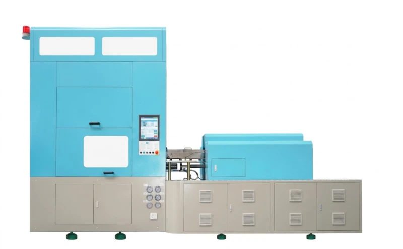
Fig. 2 — The HGY150-V4-EV 4-station fully servo machine. Its 392g injection capacity and dual servo clamping system support up to 8 cavities for 30ml bottles, delivering theoretical output of up to 6,400 BPH. The full servo drive (10 servo axes) also reduces non-productive motion time by 10–15% compared to hydraulic equivalents, directly improving cycle time.
6. OEE and Line Efficiency: From Theoretical to Actual Output
Overall Equipment Effectiveness (OEE) is the ratio of actual output to theoretical maximum output over a given period. It captures three distinct losses that reduce real-world production below the theoretical figure:
Planned uptime minus unplanned stoppages (breakdowns, material outages, changeovers). Typical ISBM availability: 88–95%
Actual cycle time versus ideal cycle time. Includes slow running during startup and minor speed reductions. Typical ISBM performance: 90–96%
Good bottles produced versus total bottles produced. Rejects from startup, parameter drift and process upsets. Typical ISBM quality rate: 97–99.5%
OEE Formula
OEE = A × P × Q
Typical well-run ISBM line: 0.91 × 0.93 × 0.985 = OEE 0.834
For production planning purposes, use an OEE of 0.80 for new lines (while operators are still on the learning curve) and 0.85 for established lines with experienced operators and a functioning preventive maintenance programme. Do not plan against theoretical output — a capacity plan built on 100% theoretical output will miss its targets every month.
7. Auxiliary Constraints: How Air Supply Limits Peak Output
One of the most frequently overlooked output constraints is the compressed air supply. ISBM stretch blow stations consume high-pressure air (typically 2.0–3.5 MPa) in bursts — one burst per cycle, with all cavities blowing simultaneously. The peak instantaneous flow demand during the blow phase can be three to five times the average flow demand over the full cycle.
If the air supply system cannot deliver the peak flow without a pressure drop, two failure modes occur: the blow pressure falls below the minimum required to fully expand the preform against the mould cavity (resulting in short-blown bottles with thick walls and visible underfill), or the cycle time extends while the machine waits for pressure to recover between shots (directly reducing BPH).
Air compressor sizing rule: Size your oil-free air compressor for ISBM at a minimum of 1.5 times the machine’s published average air consumption, and pair it with a receiver tank of at least 500 litres to buffer peak demand. An undersized compressor is the most common reason for an ISBM line running consistently below its theoretical output despite correct machine settings.
| Machine | High-P Air Consumption | Recommended Compressor | Receiver Tank |
|---|---|---|---|
| HGY50-V3-EV | 100 L/min | 7.5 kW / 150 L/min | 300 L |
| HGY150-V4 | 300 L/min | 22 kW / 450 L/min | 500 L |
| HGY150-V4-EV | 350 L/min | 22 kW / 500 L/min | 500 L |
| HGYS280-V6 | 800 L/min | 55 kW / 1,200 L/min | 1,000 L |
8. Worked Example: Sizing a Machine for 5 Million Bottles per Year
A cosmetic brand requires 5,000,000 units per year of a 50ml PETG serum bottle, preform weight 12g. The factory operates 20 hours per day, 300 days per year (6,000 production hours annually). Applying the formulas step by step:
-
1Required hourly output5,000,000 ÷ 6,000 hours = 833 bottles per hour minimum actual output (before OEE factor).
-
2Apply OEE factorAt OEE 0.82, required theoretical BPH = 833 ÷ 0.82 = 1,016 theoretical BPH.
-
3Estimate cycle time for this bottle50ml PETG at 12g preform: injection time approximately 5.5–6.5s (dominant station). Use 6.0s as the planning cycle time.
-
4Calculate required cavity countN = (BPH × CT) ÷ 3,600 = (1,016 × 6.0) ÷ 3,600 = 1.69 cavities. Round up to 2 cavities minimum.
-
5Machine selectionA 2-cavity mould on the HGY50-V3-EV (239g injection capacity; 2 cavities × 12g = 24g, well within range) delivers theoretical BPH = (3,600 ÷ 6.0) × 2 = 1,200 BPH. At OEE 0.82: 984 actual BPH. This exceeds the 833 BPH target. Recommended: HGY50-V3-EV with 2-cavity mould.
-
6Capacity headroom984 actual BPH vs 833 required = 18% headroom. Sufficient buffer for unplanned downtime, product launches and volume growth within the planning horizon without additional capital expenditure.
Theoretical BPH = (3,600 ÷ Cycle Time) × Cavities
Actual BPH = Theoretical BPH × OEE (use 0.80–0.85)
Annual volume = Actual BPH × Hours/Day × Days/Year
Required cavities = (Required BPH × Cycle Time) ÷ 3,600 — then round up
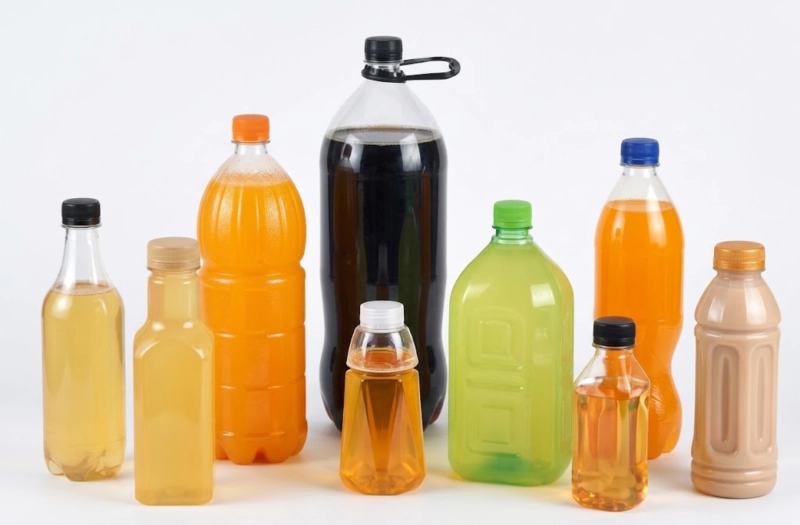
Fig. 3 — PET and PETG bottle samples produced by one-step ISBM. Output rates for containers in this volume range (30–200ml) are determined primarily by preform injection time and cavity count — not by the blow station, which is typically faster than injection for standard thin-walled geometries.
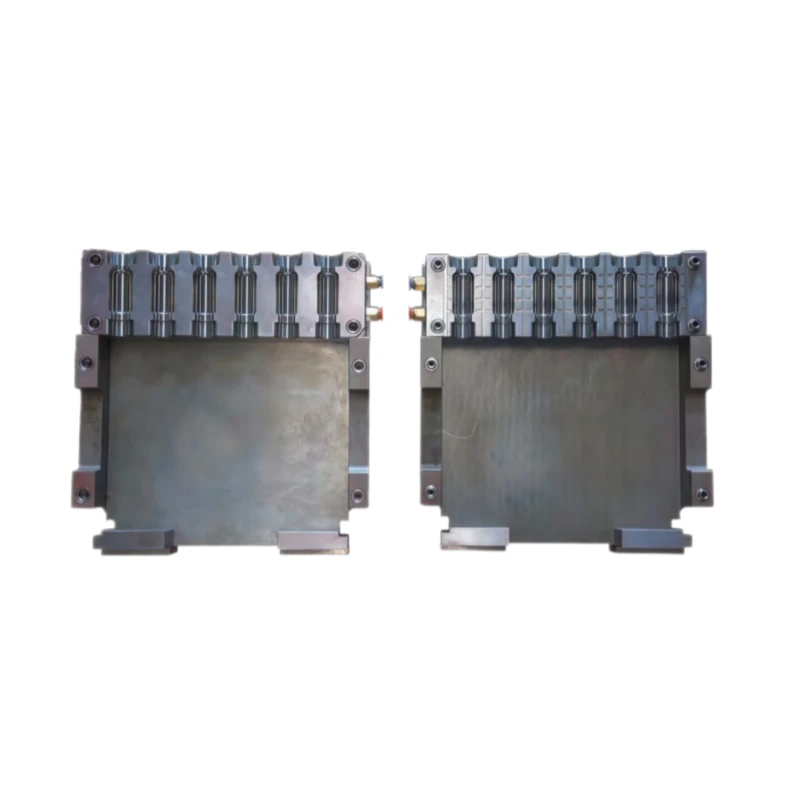
Fig. 4 — ISBM preform injection mould (left) and blow mould set (right). The cavity count in both moulds must match — adding a cavity to one without the other is not possible. Mould investment is typically the highest single cost in an ISBM project after the machine itself, making cavity count selection a critical capital efficiency decision.
Need an Output Calculation for Your Specific Bottle?
Send us your bottle volume, preform weight estimate, resin type and annual volume target. Our engineers will calculate the recommended cycle time, cavity count and machine platform — and confirm whether the numbers work for your production plan.