
In one-step injection stretch blow molding, the preform is not an intermediate product — it is the template from which every quality characteristic of the finished bottle is determined. Wall thickness distribution, neck geometry, gate position and thermal profile are all locked in at the preform stage, before a single millimetre of stretch has occurred. Getting these parameters right means flawless bottles at every cavity. Getting them wrong means no amount of downstream adjustment will rescue the output. This guide covers the engineering fundamentals of ISBM preform design and the five critical parameters that every process engineer and procurement team should understand before specifying or operating a machine.
1. What Is the ISBM Preform and Why Does Its Design Matter?
In the one-step ISBM process, the preform is the thick-walled intermediate tube that is injection-moulded at Station 1 and immediately transferred — still at elevated temperature — to the stretch blow moulding station. Unlike the two-step (reheat blow) process where preforms are produced separately, cooled to room temperature and reheated later, the one-step preform retains its residual injection heat throughout the process. This thermal continuity is the defining advantage of one-step ISBM — but it also means that any deficiency designed into the preform cannot be corrected downstream.
The preform geometry determines three outcomes simultaneously: how the material will stretch, where the wall thickness will be concentrated in the finished bottle, and how optically clear the final container will be. A preform that is too short stretches beyond its optimal orientation window; one with uneven wall thickness produces bottles that fail drop tests on the thin side while wasting material on the thick side.
Key engineering principle: In ISBM, the preform is the bottle in embryonic form. Every decision made at the preform design stage — wall thickness, length, neck dimensions, gate position — is a permanent commitment. There is no second chance after injection.
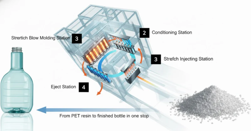
Fig. 1 — One-step ISBM 4-station process flow. The preform is formed at Station 1 and reaches the blow station while still retaining residual injection heat — eliminating the reheating step that characterises two-step processes.
2. Wall Thickness Distribution: The Foundation of Bottle Quality
Wall thickness in the preform directly determines wall thickness in the finished bottle — but the relationship is not linear. During the stretch blow phase, the polymer is simultaneously stretched axially (by the stretch rod) and radially (by blow air pressure at 2.0–3.5 MPa), and material flows towards regions of least resistance. A preform with uniform wall thickness will not necessarily produce a bottle with uniform wall thickness, because the geometry of the blow mould creates local stretch ratios that vary across the bottle body. Consistent blow air pressure is a prerequisite for repeatable wall thickness results — pressure fluctuations as small as ±0.2 MPa can shift wall distribution by 8–12% at the bottle shoulder. A stable, matched-capacity matched air compressor system is therefore part of the preform quality system, not simply a utility supply.
2.1 Calculating Target Wall Thickness
The starting point is the desired finished bottle wall specification — typically 0.25mm to 1.2mm for standard cosmetic and pharmaceutical bottles, and up to 3mm for thick-walled premium packaging. Working backwards from the finished wall target using the expected stretch ratios gives the required preform wall:
| Bottle Type | Axial Stretch | Radial Stretch | Target Wall | Preform Wall |
|---|---|---|---|---|
| Standard cosmetic serum (30ml) | 2.5x | 3.0x | 0.5mm | 3.5 – 4.0mm |
| Premium thick-wall lotion (150ml) | 2.0x | 2.5x | 1.2mm | 5.5 – 6.5mm |
| Pharmaceutical syrup bottle (100ml) | 2.8x | 3.2x | 0.4mm | 3.5 – 4.5mm |
| Water bottle (500ml PET) | 3.0x | 3.5x | 0.3mm | 3.0 – 3.8mm |
| Wide-mouth food jar (250ml) | 1.8x | 2.2x | 1.5mm | 5.5 – 7.0mm |
2.2 The Graded Wall Profile
For most bottle geometries — particularly those with a shoulder transition, a body taper or an oval cross-section — a uniform preform wall thickness is not the correct design. A graded wall profile, where the preform is deliberately thicker at the bottom and thinner at the shoulder zone, compensates for the differential stretch that occurs as the preform expands into the blow mould cavity. This produces a more uniform finished bottle wall despite the irregular geometry.
The graded profile is achieved through variations in the injection mould core pin geometry — the tapered core pin is the most common approach, producing a preform that is thicker at the closed end (future bottle base) and progressively thinner towards the neck.
A wall thickness deviation of more than 15% between the thinnest and thickest points of the finished bottle body is typically the acceptance threshold for premium cosmetic and pharmaceutical packaging. Achieving this from a uniform preform wall requires either very symmetrical bottle geometry or a precisely graded core pin profile.
3. Gate Location: How Injection Point Affects Clarity and Stress
The gate is the point at which molten resin enters the preform cavity from the hot runner system. In IBM and ISBM, the gate is invariably located at the base of the preform — the future bottle base — for a fundamental reason: this is the only location that allows the gate vestige (the frozen remnant of the injection point) to be completely enclosed within the stretched and thinned bottle base, where it is invisible from the side and does not affect the bottle’s functional sealing surfaces.
3.1 Gate Types and Their Trade-offs
Three gate configurations are used in ISBM preform moulds, each with different implications for optical clarity and residual stress:
-
APin Gate (Point Gate)The most common configuration — a small-diameter gate (typically 0.8–1.5mm) at the geometric centre of the preform base. Produces the smallest gate vestige and the most uniform radial flow front, giving the best optical clarity in the finished bottle base. Preferred for cosmetic and pharmaceutical applications.
-
BValve Gate (Needle Valve Gate)A mechanically actuated gate that closes cleanly after injection, leaving essentially no vestige. Used for clarity-critical applications where even a pin gate mark is unacceptable — typically high-end perfume bottles. Requires a valve gate hot runner system, increasing tooling cost but significantly improving base clarity.
-
COffset GateA gate positioned off-centre, used for geometrically asymmetric bottles where a centred gate would produce uneven flow. Requires careful balancing in a multi-cavity tool — an offset gate in one cavity must be mirrored consistently across all cavities to maintain fill balance and gram weight consistency.
3.2 Gate Diameter and Shear Rate
Gate diameter has a direct relationship with shear rate — the rate at which polymer chains are deformed as they pass through the gate orifice. Excessive shear rate generates localised heat, which in PETG and PET can cause polymer degradation (yellowing), stress whitening and reduced clarity. For PETG specifically, the recommended maximum gate shear rate is approximately 40,000 s⁻¹ — above this threshold, visible haze appears at the bottle base regardless of downstream process settings.
PETG gate diameter guideline: For PETG preforms of 15–30g, a minimum gate diameter of 1.2mm is typically required to keep shear rate within the optical clarity window. For heavier preforms (50g+), increase to 1.5–2.0mm and consider a valve gate configuration.
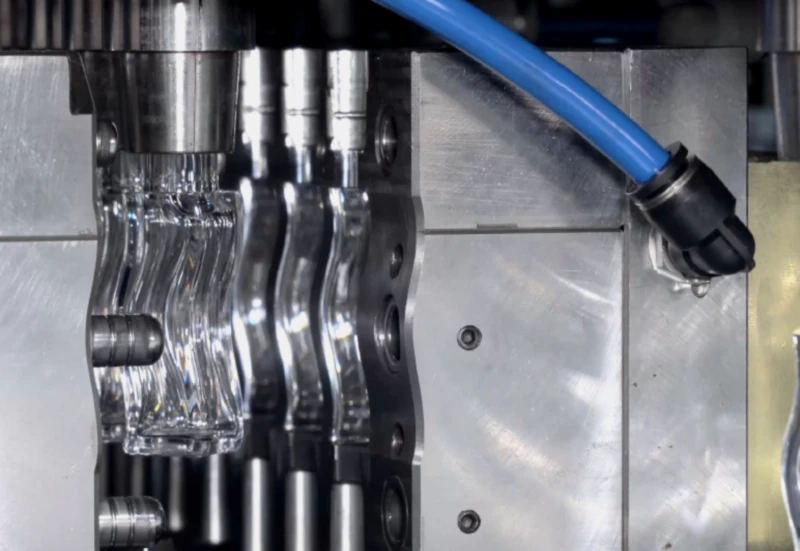
Fig. 2 — ISBM preform injection mould components: the core pin (centre) forms the inner preform surface and determines wall thickness profile; the neck ring (surrounding) locks in the final thread geometry at injection. Gate location is at the base of the core pin, shown at the bottom of the assembly.
4. Neck Geometry: Setting Thread and Sealing Surface at Injection
One of the defining technical advantages of the ISBM process is that the bottle neck — thread profile, sealing surface, neck height, and neck diameter — is formed entirely at the injection station and never subsequently stretched or deformed. This is fundamentally different from two-step reheat blow moulding, where the neck is set during preform injection but then must survive the reheating oven without distortion. In ISBM, the neck travels from injection to blow station at controlled temperature, and the neck ring holds the geometry precisely throughout.
4.1 Neck Diameter and Machine Compatibility
The neck diameter is the first constraint in preform design, because it must fall within the machine’s neck ring accommodation range. For the HGY50-V3-EV (3-station), the supported neck diameter range is 17mm to 60mm; for the HGY150-V4 and V4-EV (4-station), 17mm to 83mm. For IBM machines in the ZQ series, the neck range extends from 7mm (the eye dropper minimum) up to 120mm for wide-mouth containers.
4.2 Thread Profile Standards
The thread standard must be specified before mould design begins. Common international standards encountered in cosmetic and pharmaceutical applications include GPI 20/410 (the most common pump bottle standard), GPI 24/410, DIN EN ISO 8317 (child-resistant closures) and PCO-1881 (the standard PET water bottle finish). Each standard has a defined thread pitch, number of starts, and sealing surface geometry — any deviation at the mould design stage translates directly into closure fit failures in production.
| Standard | Neck Diameter | Thread Turns | Typical Application |
|---|---|---|---|
| GPI 20/410 | 20mm | 1.8 | Pump dispensers, cosmetics, pharma |
| GPI 24/410 | 24mm | 1.8 | Lotion pumps, large dispensers |
| GPI 28/410 | 28mm | 1.8 | Wide-mouth cosmetics, food |
| PCO-1881 | 28mm | 1.8 | PET water and beverage bottles |
| DIN 168 / ISO | Variable | Variable | Pharmaceutical, child-resistant |
| Custom / Brand | As designed | As designed | Premium fragrance, luxury cosmetics |
5. The 5 Critical Parameters That Determine Bottle Quality
Beyond the structural design decisions of wall thickness, gate location and neck geometry, five process parameters at the injection station determine whether a correctly designed preform actually delivers the bottle quality it was engineered to produce. These parameters must be established during trial production and verified before any volume production run begins.
Controls polymer flowability and shear heat generation. Too low: incomplete fill, short shots, and elevated injection pressure. Too high: polymer degradation, yellowing (PET/PETG acetaldehyde generation), and reduced molecular weight that weakens the finished bottle. The target is the lowest temperature that achieves complete, balanced fill across all cavities.
Determines how quickly the melt fills the cavity and how well it replicates the mould surface detail, particularly in fine thread profiles. Too fast: jetting, weld lines and surface defects. Too slow: premature freeze-off before complete fill, especially in thin-wall sections. Multi-stage injection (fast fill / slow pack) is standard for ISBM preforms.
Compensates for volumetric shrinkage as the melt cools and solidifies. Insufficient holding pressure causes sink marks, voids (internal bubbles) and under-filled neck threads. Excessive holding pressure creates internal stress that manifests as stress whitening or crazing after stretch blowing — particularly critical for PC and Tritan processing.
The mould temperature profile controls how quickly the preform skin solidifies and how much residual heat is retained for the stretch blow station. The neck ring must be the coldest zone — the neck geometry must be fully frozen before transfer. The preform body must retain sufficient heat for stretching. This thermal gradient is the critical parameter that separates 3-station from 4-station machine performance.
The screw recovery phase determines the homogeneity and temperature consistency of the melt shot. Back pressure controls the degree of mixing and shear heating during plasticisation — higher back pressure improves melt homogeneity but increases shear heating, which must be compensated by reducing barrel temperature. Screw speed has a similar trade-off. Decompression (suck-back) after recovery prevents drool at the nozzle tip, which would introduce cold material into the next shot and cause surface defects or uneven gram weight. For PETG and PC, which are sensitive to thermal history, keeping screw recovery parameters conservative is more important than optimising cycle time.
Auxiliary system note — blow air supply: The stretch blow station operates at 2.0–3.5 MPa high-pressure air and requires a clean, dry, oil-free supply to prevent contamination of food-grade, pharmaceutical and cosmetic containers. For PETG and PC production in particular, oil carryover from a standard lubricated compressor will cause surface haze and adhesion failures in downstream decoration. We recommend pairing ISBM machines with a dedicated oil-free air compressor for ISBM sized to the machine’s peak flow demand, with an integrated air dryer and receiver tank to buffer pressure during high-cavity simultaneous blow cycles.
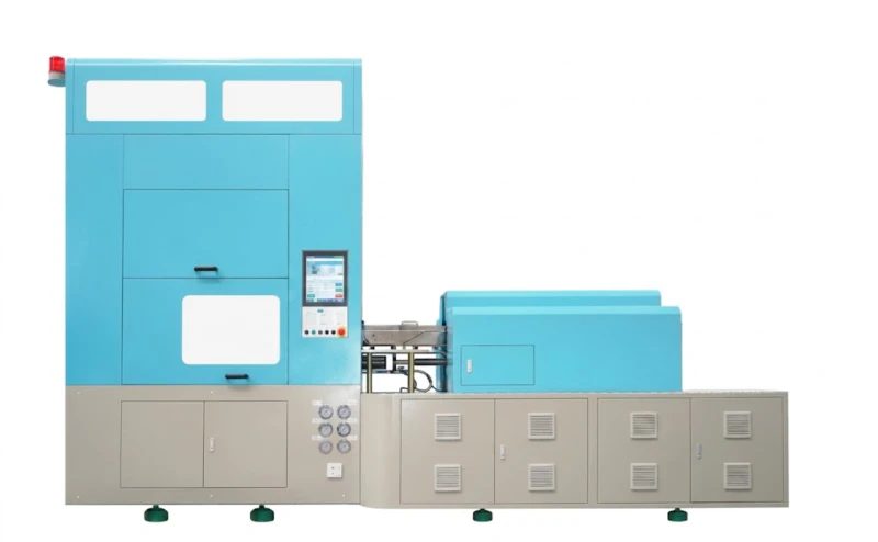
Fig. 3 — The HGY150-V4-EV 4-station fully servo ISBM machine. The dedicated temperature conditioning station allows precise thermal management between injection and stretch blowing — a capability absent in 3-station machines that makes 4-station machines the correct choice for thick-walled and complex preform geometries.
6. ASB Mold Preform Design: Compatibility Considerations
For customers who own existing Japanese Nissei ASB molds and are evaluating our ISBM machines as a replacement or supplementary platform, preform design compatibility is the central technical question. Our 4-station machines — specifically the HGY150-V4 and HGY150-V4-EV — are engineered to accept ASB-12M, ASB-70DPH and ASB-250 interface dimensions directly, without modification to the mold.
However, there are preform design considerations specific to ASB mold migration:
- ✓The preform wall thickness profile designed for an ASB machine assumes the same injection pressure range and cooling efficiency as the original equipment. Our machines use equivalent servo pump pressures (up to 150KN injection clamping on the HGY150-V4), so preform fill parameters transfer directly in most cases.
- ✓The neck ring cooling channel configuration in ASB molds is designed around ASB’s cooling water flow rate specifications. Our machines supply cooling water at 0.4–0.6 MPa — confirm this is within the mold’s design specification before installation.
- ✓Gram weight (shot weight) must be re-verified on our machine, because the hot runner temperature calibration differs from ASB’s original system. Allow one trial run to recheck fill balance across all cavities before committing to production parameters.
- ✓ASB preform designs typically assume a 4-station conditioning station. Customers running ASB molds on our 3-station HGY50-V3-EV should verify that their bottle geometry is achievable without the dedicated conditioning step — thick-walled and asymmetric bottles almost always require the 4-station platform.
7. Common Preform Design Defects and How to Avoid Them
The following defects originate at the preform design or process parameter stage — they cannot be corrected by adjusting the stretch blow parameters downstream.
- →Weld lines (knit lines): Caused by two flow fronts meeting inside the cavity after flowing around an obstruction. The weld line translates to a weak point in the finished bottle. Solution: Review gate position and flow simulation; increase melt temperature by 5–10°C at the weld line zone.
- →Sink marks on preform body: Caused by insufficient holding pressure or holding time. In the finished bottle, sink marks become visible distortions on the body surface. Solution: Increase holding pressure by 10–15% and extend holding time until the gate freezes solid.
- →Base clarity failures (haze): Caused by excessive gate shear rate, polymer degradation from overheating, or moisture in the resin. For PETG, moisture above 0.04% at processing causes hydrolytic degradation irreversible by any downstream adjustment. Solution: Verify drying time and temperature; increase gate diameter if shear rate exceeds 40,000 s⁻¹.
- →Uneven wall thickness distribution: Caused by core pin misalignment, non-uniform injection fill across cavities, or incorrect preform L/D ratio. Solution: Check core pin concentricity; run a fill balance test with short shots; review preform L/D ratio against the stretch ratio requirements.
- →Neck distortion during transfer: Caused by insufficient neck ring cooling — the neck geometry is not fully frozen before the rotary table transfers the preform. Solution: Reduce neck ring cooling water temperature by 3–5°C; check cooling water flow rate; increase cooling time if the injection station cycle allows.
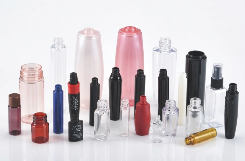
Fig. 4 — Finished PETG cosmetic bottles produced by one-step ISBM. The crystal-clear transparency and invisible parting lines are the direct result of correct preform wall design, gate configuration and process parameter control — particularly melt temperature within the optical clarity window and gate shear rate below 40,000 s⁻¹.
8. Engineering Checklist Before Production
Before committing to volume production on a new ISBM preform design, the following checklist should be completed and documented:
-
1Stretch ratio verificationCalculate axial and radial stretch ratios from preform dimensions and bottle geometry. Confirm both ratios fall within the optimal orientation window for the specified resin (PET: axial 2.5–3.5x, radial 3.0–4.0x; PETG: axial 2.0–3.0x, radial 2.5–3.5x).
-
2Wall thickness measurement — preform and bottleMeasure preform wall at 5 points (base, lower body, mid-body, upper body, below neck) using an ultrasonic gauge. Measure finished bottle at the same 5 corresponding zones. Maximum acceptable deviation from target: ±15% at any point.
-
3Gram weight consistency across all cavitiesWeigh 10 preforms from each cavity in a multi-cavity tool. Maximum acceptable gram weight variation between cavities: ±1.5%. Larger variation indicates runner imbalance requiring hot runner temperature adjustment.
-
4Neck dimension checkMeasure thread outer diameter, thread height, sealing surface inner diameter and neck height on 10 consecutive bottles. Compare against the applicable standard (GPI/PCO/DIN) and verify closure fitment with production caps or pumps.
-
5Drop test and pressure testConduct drop test (filled bottle, 1.2m onto concrete, 6 orientations) and pressure test (for carbonated or vacuum applications) on a minimum of 20 bottles from each cavity before release for production. Document pass/fail by cavity to identify any systematic mould variation.
ISBM preform design is not a standalone exercise — it is a systems problem that connects resin selection, injection mould engineering, machine capability and process parameter setting into a single integrated outcome. The five critical parameters (injection temperature, injection pressure/speed, holding pressure/time, mould temperature profile, and screw recovery settings) are the levers through which a correctly designed preform is consistently converted into a correctly formed bottle. Understanding their individual roles and interactions is the foundation of reliable ISBM production.
Have a Bottle Design That Needs ISBM Preform Engineering?
Send us your bottle drawing, target resin, volume, wall thickness and closure specification. Our engineers will advise on preform geometry, gate configuration, machine platform and mold tooling — typically within 24 hours.