
A Root-Cause-First Diagnostic Framework for IBM Container Defects — Because Adjusting Parameters Without Identifying the Cause Fixes Nothing and Wastes Production Time
IBM production defects are rarely random. Each defect type has a specific set of root causes — drawn from process parameters, tooling condition, material properties, and machine state — and the correct corrective action can only be identified after the root cause is correctly identified. The most common and costly IBM troubleshooting error is adjusting the first plausible parameter (usually injection pressure or melt temperature) without first establishing which specific cause is responsible for the observed defect. This approach sometimes masks the symptom temporarily while leaving the root cause in place to produce the defect again — or introduces secondary problems while correcting the first.
This guide presents a structured, root-cause-first diagnostic approach to the twelve most common IBM production defects. For each defect, it describes the visual characteristics that identify it, the complete set of potential root causes in priority order of likelihood, the diagnostic tests that distinguish between root causes, and the specific corrective actions for each confirmed cause. The goal is to get from defect observation to confirmed root cause to effective correction in the minimum number of production trials.
1. The Diagnostic Framework: Root Cause Before Correction
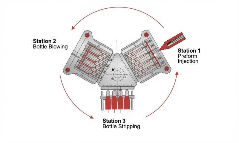
Before applying any corrective action, three diagnostic questions must be answered in sequence:
Which station is the origin?
Most IBM defects originate at a specific station. Short shots, flash, sink marks, and neck dimension issues originate at Station 1. Body surface defects, wall thickness variation, and incomplete inflation originate at Station 2. Stripping damage originates at Station 3. Identifying the station of origin directs the search to the correct tooling and parameter set.
Is the defect in all cavities or specific cavities?
A defect in all cavities simultaneously points to a process parameter root cause (barrel temperature, injection pressure, cooling dwell, blow pressure). A defect in one or two specific cavities points to a tooling root cause (core pin damage, cavity dimensional deviation, runner imbalance, blocked cooling channel in that cavity). This single distinction eliminates half the potential root cause list immediately.
Did the defect appear suddenly or gradually?
A defect that appears suddenly (between one shift and the next, or after a material lot change) points to a changed input: new resin lot, resin moisture content, parameter change, or tooling damage event. A defect that has gradually worsened over weeks or months points to wear-related causes: core pin dimensional drift, cavity polish degradation, cooling channel fouling, or barrel/screw wear. The onset pattern determines the investigation direction.
The documentation requirement: Effective IBM troubleshooting requires accurate, time-stamped records of: when the defect was first observed, which cavities are affected, what parameter changes preceded the defect onset, and what corrective actions were taken and their results. Without this data, the same defect will recur and the same diagnostic process will be repeated unnecessarily. Implement a production defect log as a standard operating procedure before the defect situation arises — not during a production crisis.
2. Defect 1 — Short Shot (Incomplete Parison Fill)
Visual identification
Parison is visibly incomplete — the tip zone of the core pin is not covered by melt, leaving a visible void or thin membrane at the parison base. The resulting blown container has a hole or extremely thin punctured zone at the base. In severe cases, the parison falls off the core pin before reaching the blow station.
| Root Cause | All Cavities? | Diagnostic Test | Corrective Action |
|---|---|---|---|
| Insufficient injection pressure | Yes | Check actual injection pressure against setpoint on machine display during fill | Increase injection pressure in 5% increments until fill is complete; verify no flash develops |
| Melt temperature too low | Yes | Measure actual melt temperature with pyrometer at nozzle; compare to setpoint | Increase barrel zone setpoints by 5 to 10 degrees C; allow 10 cycles for equilibrium before assessment |
| Injection speed too low (freeze-off before fill) | Yes | Monitor fill time on machine; if above 1.2 s for small containers, speed is likely low | Increase injection speed in 10% increments; watch for burn marks indicating excessive shear at high speed |
| Gate diameter too small (freeze-off before pack) | Specific cavities or all | Measure gate diameter on mould — compare to specification; check for gate land contamination | Clean gate land; if under-size, requires tooling modification (gate opening) |
| Insufficient shot size / decompression too large | Yes | Weigh parisons — if consistently underweight, shot size is the issue | Increase shot size in 2% increments; reduce decompression stroke if it is pulling melt back excessively |
| Resin moisture (excessive steam voids) | Yes — irregular pattern | Inspect parison surface for silver streaks or bubbles; check resin moisture with moisture analyser | Pre-dry resin to specification (PP: max 0.02% moisture; HDPE: max 0.02%; PET: max 0.005%) |
3. Defect 2 — Flash at Parting Line or Gate
Visual identification
Thin fins or webs of plastic extending beyond the container surface at the injection cavity parting line (typically at the neck thread flanks), at the gate vestige on the container base, or at the blow cavity parting line on the container body shoulder. Flash at the neck thread is a functional defect — it prevents correct closure engagement.
| Root Cause | Location | Diagnostic Test | Corrective Action |
|---|---|---|---|
| Injection pressure too high | Neck parting line | Reduce injection pressure 5%; if flash reduces, pressure is the cause | Reduce injection pressure to minimum that maintains complete fill; adjust injection speed to compensate |
| Clamping force insufficient for cavity pressure | Neck parting line — all cavities | Calculate required clamping force: F = P x A x N x 1.3 x 0.1; compare to machine rated force | If clamping force is insufficient, reduce injection pressure or cavity count; consider machine upgrade |
| Worn parting line (cavity wear) | Specific cavity parting line | Inspect parting line surface with magnification; measure parting line flatness | Tooling maintenance: regrind and re-lap parting line surfaces; replace cavity insert if wear is beyond regrind |
| V-P switchover too late | Gate area / base | Advance V-P switchover position by 2% of stroke; if flash reduces, switchover timing is the cause | Advance V-P switchover in 1% increments until flash disappears without short-shot developing |
| Melt temperature too high (lower viscosity) | All parting lines | Measure actual melt temperature; if more than 15 degrees C above minimum fill temperature, reduce | Reduce barrel setpoints by 10 degrees C; verify complete fill is maintained at lower temperature |
4. Defect 3 — Sink Marks on Parison or Container Base
Visual identification
Localised depressions or concave dimples on the parison outer surface (visible after injection, before blowing) or on the finished container base in the gate area. The depression results from volumetric shrinkage of the polymer skin pulling inward as the hotter core material beneath cools and contracts after the gate has frozen.
Root cause: Insufficient hold pressure or hold time
Diagnostic: Increase hold pressure 10% for 10 cycles — if sink marks reduce or disappear, hold pressure is insufficient. Correction: Increase hold pressure until sink marks are eliminated; verify that increased hold pressure does not produce flash at the parting line. Alternatively, extend hold time in 0.1 s increments until gate freeze is confirmed — verified by parison weight stability across the hold time increase.
Root cause: Premature gate freeze (gate diameter too small)
Diagnostic: Sink marks that do not respond to hold pressure increase indicate gate freeze before adequate pack. Check gate diameter: if below 50% of minimum neck wall thickness, gate is too small. Correction: Tooling modification — enlarge gate diameter. Interim measure: increase melt temperature slightly to slow gate freeze rate while tooling is modified.
Root cause: Excessive wall thickness at sink location (thick-wall design)
Diagnostic: Measure wall thickness at the sink location. If above 3.0 mm, the through-thickness temperature gradient during cooling is large enough to cause inner-core shrinkage after the skin freezes. Correction: Tooling modification to reduce wall thickness in the affected zone; or extend injection cooling dwell to allow more complete through-thickness solidification before ejection.
Root cause: V-P switchover too early (insufficient fill before pack)
Diagnostic: Sink marks in the furthest-from-gate zone (parison tip) that respond to later V-P switchover position. Correction: Delay V-P switchover position by 2% of stroke increments until sink marks disappear; verify no flash develops at the new switchover position.
5. Defect 4 — Neck Dimension Drift (T, E, or I Out of Specification)
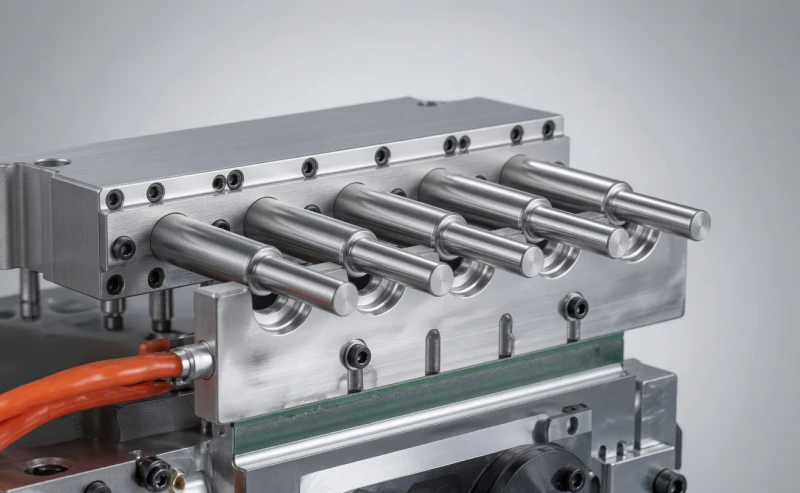
Neck dimension drift is one of the most commercially critical IBM defects because it directly affects closure compatibility, CRC function, and IPC specification compliance. The dimension drifting and direction of drift are the primary diagnostic inputs:
| Drift Pattern | Most Likely Root Cause | Diagnostic Test | Corrective Action |
|---|---|---|---|
| T and E both increasing (neck widening) | Injection cavity wear (cavity has grown); or melt temperature too high causing thermal expansion | Measure cavity T and E dimensions off-machine with CMM; compare to drawing | If cavity worn: tooling refurbishment. If thermal: reduce melt and mould temperature |
| I decreasing (neck bore narrowing) | Core pin diameter increasing due to thermal expansion; or resin build-up on core pin | Measure core pin diameter when cold; inspect for resin residue on DLC surface | Clean core pin; verify core pin temperature is stable; confirm mould temperature is within specification |
| T in-spec but neck height H short | Insufficient injection cooling dwell — neck deforms axially during table index | Increase cooling dwell by 0.3 s; if H returns to specification, cooling is the cause | Increase injection cooling dwell to stabilise neck; improve coolant temperature or flow rate to recover cycle time |
| Drift in specific cavities only | Blocked cooling channel in specific cavity reducing local cooling rate; or individual cavity dimensional deviation | Measure coolant flow rate per cavity circuit; measure cavity temperature with IR thermometer per cavity | Descale or unblock specific cavity cooling circuits; regrind specific cavity if dimensionally deviant |
| All dimensions drifting gradually over weeks | Progressive cavity wear from high-cycle production; or progressive core pin dimensional drift from DLC depletion | CMM measurement of cavity and core pin dimensions; compare to historical records | Schedule planned tooling refurbishment; do not allow drift to exceed 50% of total tolerance before corrective action |
6. Defect 5 — Uneven Wall Thickness Distribution
Uneven wall thickness in the blown container body — thicker on one side, thinner on the opposite — is a common IBM quality issue with several distinct causes. The position of the thick zone relative to the container geometry is the primary diagnostic clue:
Thick zone: consistently one side around full height
Cause: Core pin eccentricity — the core pin is not centred within the injection cavity, producing a parison that is thicker on one side. Diagnosis: Measure core pin concentricity within the injection cavity using feeler gauges or CMM. Correction: Adjust core pin seating or re-machine core pin mount bore to restore concentricity within 0.05 mm.
Thick zone: at the base, thin zone at the shoulder
Cause: Parison axial wall thickness gradient — the gate end of the parison (base) is thicker due to slow fill or late V-P switchover, while the distal end (shoulder) is thinner. Diagnosis: Examine the parison before blowing — check for visible thickness gradient along length. Correction: Increase injection speed to improve melt distribution along the core pin; optimise V-P switchover position.
Thick zone: adjacent to blow air vent side
Cause: Blow cavity venting inadequacy — air trapped on the non-vent side prevents complete inflation, causing the parison to contact the cavity preferentially on the vented side and produce thicker walls there. Diagnosis: Inspect blow cavity vent slots; measure vent depth (should be 0.015 to 0.04 mm). Correction: Clean vents; deepen if worn below 0.01 mm; add vent on the thick-zone side.
Wall variation worsening at high production temperature
Cause: Thermal expansion of core pin or carrier assembly at elevated operating temperature changing effective concentricity. Diagnosis: Measure wall distribution at machine cold start and again after 2 hours of production — if variation is worse at temperature, thermal expansion is the cause. Correction: Add cooling to the core pin carrier or table assembly; reduce mould temperature; verify coolant supply is maintaining steady-state temperature.
7. Defect 6 — Surface Haze, Matt Patches, or Orange-Peel Texture

Orange-peel or rough texture over the full body surface
Cause: Inadequate blow cavity venting — trapped air between the parison outer surface and the cavity wall prevents full surface contact, so the container surface copies the air-roughened parison surface rather than the polished cavity surface. Diagnosis: Run a short-shot blow trial at 80% of full blow pressure; examine the partially inflated container — if the surface roughness corresponds to zones of last contact, venting is the cause. Correction: Clean blow cavity vents; deepen if under 0.015 mm depth; add additional vent positions at the maximum body diameter and base corner.
Localised matt patches at specific body zones
Cause: Blocked vent at a specific location causing localised air entrapment. Diagnosis: The matt patch location matches the blocked vent position. Remove blow cavity insert and inspect vents under magnification. Correction: Clean specific blocked vent using compressed air and fine wire; re-assemble and verify surface quality improvement.
Surface haze that worsens at higher production speeds
Cause: Insufficient blow dwell at high cycle speeds — the container body is not adequately cooled against the cavity before ejection, and the warm surface loses contact quality during cavity opening. Diagnosis: Increase blow dwell by 0.3 s; if surface quality improves, blow dwell was insufficient. Correction: Set blow dwell at the minimum that maintains acceptable surface quality; consider BeCu blow cavity for faster cooling if cycle time cannot be increased.
Uniform haze on transparent PET or PP containers
Cause: Mould temperature too high causing slow crystallisation (in PET) or premature haze nucleation (in PP). For PET, blow cavity temperature should be 10 to 20 degrees C; for PP, 12 to 20 degrees C. Diagnosis: Measure blow cavity surface temperature; compare to specification. Correction: Reduce blow cavity coolant temperature; verify flow rate is adequate.
8. Defect 7 — Streaks, Discolouration, or Black Specks
| Defect Appearance | Root Cause | Corrective Action |
|---|---|---|
| Silver streaks running axially from gate | Resin moisture — steam generated at gate during fill produces silver flash-lines along the flow direction | Increase pre-drying temperature and time; verify moisture content with Karl Fischer or loss-on-drying test before production |
| Black specks throughout parison surface | Thermal degradation of previous material in barrel — carbonised resin particles from overlong residence time or dead zones in barrel or hot runner | Purge barrel completely with purging compound or virgin resin at high back pressure; clean barrel and screw if purging is ineffective; reduce residence time by increasing production speed or reducing barrel zones to minimum |
| Yellow or brown discolouration, all containers | Barrel temperature too high causing thermal degradation of resin or UV stabiliser package | Reduce barrel zone setpoints to minimum fill temperature; verify actual melt temperature with pyrometer |
| Discolouration in specific cavities only | Runner dead zone or poor runner balance causing long residence time in specific branch | Inspect runner system for dead zones at branch points; re-design branch geometry to eliminate stagnant volume; increase runner temperature if using hot runner |
| Periodic single black speck in same cavity | Gate deposit accumulation and periodic dislodgement — carbonised material building up at the gate and releasing as a speck | Clean gate area; reduce injection speed through the gate zone; verify melt temperature is not excessive at the gate |
9. Defect 8 — Parison Drop During Table Index
Visual identification and consequence
The parison detaches from the core pin and falls to the machine base during the table index from Station 1 to Station 2. No container is produced on that cycle, and the fallen parison may contaminate subsequent cycles if not immediately removed. This defect typically causes the operator to stop the machine, increasing downtime and the risk of further parison drops as the machine is restarted without identifying the root cause.
Cause 1: Insufficient injection cooling dwell
The parison is still above its glass transition temperature when the table indexes — it is too soft to maintain grip on the core pin taper during the acceleration and deceleration of table rotation. Diagnosis: Increase cooling dwell by 0.5 s — if parison drop stops, cooling was the cause. Correction: Increase cooling dwell; improve coolant temperature and flow rate to recover cycle time lost from dwell increase.
Cause 2: Excessive core pin taper
A body zone taper above 2.5 degrees causes the parison to slide off the core pin under its own weight during index. Diagnosis: Measure core pin taper angle with a taper gauge or CMM; compare to drawing (should be 1.0 to 2.0 degrees on body zone). Correction: Core pin regrind to correct taper; interim measure is to increase melt temperature slightly so the parison is more compliant and grips the taper better during the brief index period.
Cause 3: DLC coating worn from core pin body zone
When the DLC coating is depleted from the core pin body, the base H13 steel surface has higher friction during contact but lower lubricity during release — paradoxically, worn DLC can cause both parison sticking (at Station 3) and parison drop (at index) depending on where the wear is concentrated. Diagnosis: Inspect DLC surface under magnification; look for dull patches indicating coating depletion. Correction: DLC recoating or core pin replacement.
Cause 4: Melt temperature too high (low viscosity parison)
Very high melt temperature produces a low-viscosity, very soft parison that cannot maintain grip on the core pin during index even with adequate cooling time. Diagnosis: Measure actual melt temperature; if more than 30 degrees C above minimum fill temperature, reduce. Correction: Reduce barrel setpoints progressively until the parison maintains reliable grip; verify complete fill is maintained at the reduced temperature.
10. Defect 9 — Inter-Cavity Weight Variation
Inter-cavity weight variation — systematic differences in container weight between cavity positions — is a runner balance issue rather than a process parameter issue and cannot be corrected by parameter adjustment alone. The diagnostic pathway is straightforward:
Inter-Cavity Weight Variation Diagnostic Sequence
1
Weigh containers from each cavity separately for 20 consecutive cycles. Calculate mean weight per cavity. If variation across cavities exceeds 3% of overall mean, runner imbalance is confirmed.
2
Identify which cavities are heavy and which are light. Map heavy cavities against the runner layout. Heavy cavities are typically nearest the sprue (shortest flow path, lowest pressure drop); light cavities are furthest from the sprue.
3
Verify that the runner layout is geometrically balanced (H-tree or equivalent symmetric branching). If the layout is a straight runner (herringbone), geometric imbalance is expected and requires either a complete runner re-design or a flow-restriction device in the short-path branches.
4
If runner is geometrically balanced but weight variation persists, investigate individual runner branch cross-sections for machining variation. Even in a symmetric H-tree, a 10% variation in runner cross-sectional area between branches produces measurable weight imbalance.
FIX
Tooling correction: adjust the cross-sectional area of specific runner branches to balance flow. In most cases this means slightly enlarging the narrow branches (shorter tool path requires less material removal) rather than reducing the wide branches. Re-weigh per cavity after each tooling adjustment until variation is within 1.5% across all cavities.
11. Defects 10 to 12 — Body Distortion, Stripping Damage, and Gate Drool
Defect 10 — Body Distortion After Ejection
The container body is out-of-round, oval, or shows localised indentations after ejection that were not present immediately after blow. The container was correctly shaped inside the blow cavity but deformed during or immediately after cavity opening.
Defect 11 — Neck or Rim Damage During Stripping
The neck thread flanks show burrs, torn material, or scuff marks. The neck rim shows compression damage or deformation. The damage is consistent across specific cavities or all cavities depending on cause.
Defect 12 — Gate Drool or Stringing Between Cycles
A fine thread or blob of melt hangs from the injection nozzle or gate between cycles, depositing a vestige on the container base or contaminating the subsequent parison. Drool occurs when the melt pressure in the barrel is not adequately relieved between injection cycles.
14. Frequently Asked Questions
Q: Multiple defects are occurring simultaneously. Where should I start troubleshooting?
When multiple defects appear simultaneously, the most productive starting point is always the defect that is blocking production — typically the most severe quality failure causing batch rejection or machine stoppage. Resolve that defect first using the root-cause diagnostic approach, then address secondary defects in order of production impact. Multiple simultaneous defects often share a common root cause: a new resin lot with different flow behaviour, a machine parameter change that affected multiple process variables, or a tooling event (impact damage, blocked cooling circuit) that cascades into multiple visible symptoms. After identifying and correcting the primary defect, re-evaluate whether secondary defects have also resolved or whether they require separate investigation.
Q: A defect appeared immediately after a resin lot change. How is this investigated?
Resin lot changes are among the most common triggers for IBM process problems because even within the same grade specification, lot-to-lot variation in melt flow index (MFI), molecular weight distribution, additive levels, and moisture content can shift the process window significantly. The diagnostic approach: (1) obtain the certificate of analysis for the new lot and compare MFI and moisture to the previous lot; (2) if MFI is higher (lower viscosity), reduce injection pressure and speed to avoid flash; if MFI is lower (higher viscosity), increase injection pressure and speed to avoid short shots; (3) verify moisture by pre-drying to specification regardless of the certificate value — moisture is the most common lot-to-lot variable not well controlled at all resin suppliers; (4) if the process window with the new lot is unacceptably narrow, contact the resin supplier with lot comparison data and request a replacement lot with tighter MFI specification.
Q: How many parameter changes should be made at one time during troubleshooting?
One change at a time — always. This is the single most important rule in IBM process troubleshooting and the one most frequently violated. Making two or more simultaneous changes means that if the defect improves, you do not know which change was responsible; if the defect worsens, you do not know which change caused it; and you may inadvertently create a new defect from the second change that masks or compounds the original. The only exceptions are: (1) when a change has a known-coupled counterpart (reducing melt temperature while increasing injection speed to compensate for higher viscosity — these are a single logical change to the process even though they affect two parameters); and (2) emergency situations where the machine must be stopped and a safe-state parameter set must be reloaded. In all other cases: change one parameter, run 20 cycles, evaluate, then change the next.
Q: Neck dimensions are within specification at the machine but fail dimensional measurement at the filling line. What causes this discrepancy?
Post-ejection dimensional change — commonly called dimensional relaxation or post-mould shrinkage — is the most frequent cause of this discrepancy. Immediately after ejection, the container dimensions reflect the tooling geometry plus any residual stress from the moulding process. Over the first 2 to 6 hours at room temperature (or faster at elevated ambient temperature), the polymer relaxes and dimensions shift. For PP pharmaceutical containers, the neck outer diameter (E) typically decreases by 0.05 to 0.15 mm over the first 4 hours post-ejection as residual injection stresses relax. If your dimensional measurement protocol samples containers immediately from the machine and the filling line samples after several hours of storage, this relaxation accounts for the discrepancy. The corrective approach: establish the stabilised dimension by measuring samples at both 0 and 4 hours post-ejection; set the machine-side IPC specification at the 0-hour value that corresponds to an acceptable 4-hour value; verify with the filling line that their gauge blocks and dimensional standards match the 4-hour stabilised geometry.
15. Conclusion: The Troubleshooting Priority Sequence
Effective IBM troubleshooting is a discipline, not a trial-and-error exercise. The difference between a process engineer who resolves a defect in 30 minutes and one who spends a shift making parameter changes without improvement is the consistent application of a root-cause-first, one-change-at-a-time diagnostic methodology. The three diagnostic questions — which station, which cavities, sudden or gradual — eliminate the majority of potential causes before a single parameter is touched.
IBM Troubleshooting Priority Sequence
Document the defect precisely: visual description, which cavities affected, onset timing, any recent changes to resin lot, process parameters, or machine maintenance. Answer the three diagnostic questions before touching the machine.
Use the cavity pattern (all vs specific) and onset pattern (sudden vs gradual) to distinguish process parameter from tooling root causes. Apply the specific diagnostic test for the suspected cause before making the correction.
Make one change at a time. Run a minimum of 20 cycles after each change before evaluating. Confirm defect elimination before declaring the root cause identified. Record the confirmed root cause and corrective action in the production defect log.
For any defect with a tooling root cause (cavity wear, core pin DLC depletion, runner imbalance): implement a proactive inspection schedule that catches the condition before it reaches defect-producing severity. The best troubleshooting is the defect that never occurs.
For IBM defects that persist after the diagnostic sequence above — or for complex multi-defect situations where the root cause is not clearly identified by cavity pattern and onset analysis — our applications engineering team provides remote process consultation and, where required, on-site troubleshooting support for ZQ-series machine installations.
IBM Process and Troubleshooting Support
Persistent IBM defects that do not respond to the standard troubleshooting framework require expert diagnosis. Our engineering team provides remote consultation, parameter review, and on-site process support for ZQ40, ZQ60, ZQ60HE, and ZQ80 series machines across all container applications.