
Mold changeover is one of the most underestimated operational costs in ISBM production. A changeover that takes four hours costs the same in lost machine time as a breakdown — but unlike a breakdown, it happens on a planned schedule and its duration is entirely within the control of the production team. The difference between a 90-minute changeover and a 4-hour changeover on the same machine, running two product changes per week, amounts to over 260 hours of lost production per year. This guide covers the engineering and procedural framework for achieving consistent sub-2-hour ISBM changeovers — from preparation through to the first good bottle of the new run.
1. What Actually Changes in an ISBM Mold Changeover
An ISBM changeover is more complex than a standard injection mold changeover because it involves three interconnected tooling assemblies that must all be swapped, aligned and verified before production can resume. Understanding what needs to change — and what does not — is the first step in reducing changeover time.
The components that change with every bottle type are:
- →Preform injection mold cavities and core pins — defines the preform geometry, weight and neck dimensions. Must match the new bottle’s preform specification exactly.
- →Neck rings — the split tooling components that form and hold the bottle neck finish (thread, sealing surface, neck height). Must correspond to the new bottle’s closure standard.
- →Stretch rods (core rods) — the mandrels that carry the preform through all stations. Rod length, diameter and tip geometry are specific to each preform and bottle combination.
- →Blow mold cavities — defines the external geometry of the finished bottle. Must be dimensionally consistent with the preform being blown into it.
- →Process parameters — injection temperature profile, holding pressure and time, mold temperatures, stretch rod speed, blow pressure profile, cycle timing. All must be set for the new preform and resin combination.
The components that typically do not change unless switching between very different resin families:
- ✓The injection screw and barrel (unless switching between incompatible resin families such as PETG to PP)
- ✓The hot runner manifold body (only the nozzle tips may need adjustment for different gate diameters)
- ✓The turntable and station indexing mechanism
- ✓The auxiliary equipment (air compressor, chiller, dryer) — though setpoints will change
The key to fast changeover: Every component that must change should be pre-staged, pre-cleaned and pre-warmed before the running machine stops. Every minute of preparation done offline is a minute saved from machine downtime.
2. Time Breakdown: Where the Hours Go
A typical unoptimised ISBM changeover takes 3.5 to 5 hours. The table below shows where that time is actually spent — and the realistic target time achievable with proper preparation and trained operators.
| Phase | Unoptimised | Target Time | Key Improvement |
|---|---|---|---|
| Preparation (offline) | 0 min (not done) | 30 min offline | Pre-stage all tooling before shutdown |
| Shutdown and purge | 30 – 45 min | 15 – 20 min | Standard purge sequence, documented setpoints |
| Mold removal | 60 – 90 min | 25 – 35 min | Quick-release clamps, dedicated mold trolley |
| New mold installation | 60 – 90 min | 25 – 35 min | Pre-warmed molds, reference alignment marks |
| Parameter setup | 45 – 60 min | 10 – 15 min | Saved recipe recall from PLC memory |
| First article and adjustment | 60 – 90 min | 15 – 20 min | Documented trial parameters, fast verification |
| Total (machine downtime) | 3.5 – 5 hours | 90 – 105 min | Preparation done offline removes 30 min from machine stop |
Single-Minute Exchange of Die (SMED) methodology — originally developed for press tooling — applies directly to ISBM. The core principle: any activity that can be done while the machine is still running should be done before it stops. In ISBM, this means staging tooling, pre-warming molds, printing parameter sheets and preparing consumables all happen during the final 30–45 minutes of the outgoing production run.
3. Phase 1 — Preparation: Everything Done Before the Machine Stops
Preparation is the single highest-leverage phase of the changeover. Every 10 minutes of offline preparation saves approximately 10 minutes of machine downtime. The following activities should be completed during the last production run, beginning 45–60 minutes before the planned shutdown:
-
1Retrieve and verify incoming toolingPull the preform mold, blow mold, neck rings and core rods for the new product from storage. Verify cavity count matches the planned production schedule. Check mold condition — any damage noted at last changeover must have been repaired before this one.
-
2Pre-warm the incoming moldsCold molds installed on a running machine create severe thermal shock and extend the time to reach stable process temperature by 30–60 minutes. Where a mold temperature controller is available offline, bring both the preform mold and blow mold to within 10°C of their target setpoints before installation. Without a mold temperature controller, bring them to at least 40–50°C using the machine’s circulation system during the shutdown phase.
-
3Print or retrieve the process recipeThe Inovance/MiRLE PLC on HGY series machines supports named recipe storage. If this product has been run before, retrieve the saved recipe and print a parameter reference sheet. If it is a new product, prepare the starting parameters based on the preform design specification — injection temperature, holding pressure, mold temperatures, blow pressure profile and cycle timing targets.
-
4Stage all tools, consumables and measuring equipmentLay out torque wrench (set to the correct mold bolt torque specification), alignment pins, water hose connectors, neck ring pins, a digital gram scale, a wall thickness gauge and the first-article acceptance criteria sheet — all within arm’s reach of the machine. Nothing should need to be fetched once the machine stops.
-
5Check resin hopper and dryerIf the new product uses a different resin (e.g. switching from PETG to PET, or between colour batches), verify the hopper is emptied and flushed before shutdown. Start drying the new resin at the correct temperature and duration at least 4 hours before the planned start of the new run. PETG requires 80°C for 4 hours minimum; PET requires 160–175°C for 4 hours minimum.
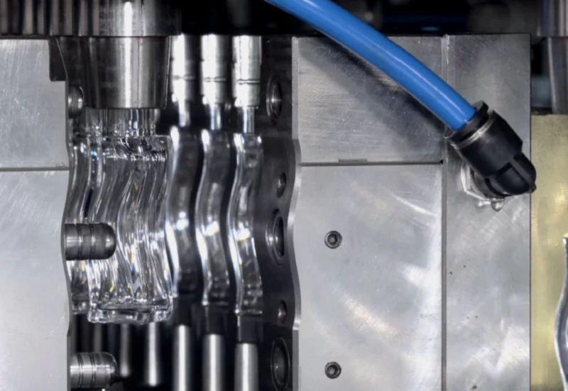
Fig. 1 — ISBM preform mold assembly: core rods (left), neck ring sets (centre) and preform cavity inserts. These three sub-assemblies must all be changed, aligned and verified in every full product changeover. Pre-staging them offline — clean, inspected and at temperature — is the single most effective changeover time reduction available.
4. Phase 2 — Controlled Shutdown and Purge
A controlled shutdown takes 15–20 minutes and leaves the machine in a clean, safe condition for mold removal. Rushing this phase by skipping the purge creates problems — contaminated hot runner channels that produce black specks in the first shots of the new run, or a barrel packed with degraded material that takes an hour to clear.
4.1 Standard Shutdown Sequence
-
1Stop material feed — run down the hopperClose the hopper gate approximately 20–30 shots before the planned stop. Allow the machine to consume the remaining material in the barrel to reduce the volume needing purging. Do not run completely empty — always leave at least one shot’s worth of material in the barrel as a cushion.
-
2Purge the barrel with purge compound or virgin resinLoad 3–5 purge shots of purge compound (or clean virgin resin of the same family) to flush the barrel and nozzle. Purge into a waste container — not into the mold. Purging is complete when the extrudate runs clear and free of colour streaks or black specks.
-
3Reduce barrel temperature and isolate hot runnerSet barrel zones to 30°C below normal processing temperature. Turn off hot runner zones individually and allow them to cool to below 80°C before disconnecting electrical connections during mold removal. Do not disconnect a hot runner connector at processing temperature — connector pins will be damaged.
-
4Disconnect cooling water and blow air circuitsClose the cooling water shut-off valves before disconnecting hoses — disconnecting under pressure saturates the mold with water and extends dry-out time on the next startup. Label all hose connections before removing them if the machine does not have colour-coded fittings.
5. Phase 3 — Mold Removal: Preform Mold, Blow Mold and Neck Rings
Mold removal is the most physically demanding phase and the one where most time is wasted through poor organisation, missing tools and improper handling. The correct removal sequence avoids damage to the machine and tooling and leaves the station in a clean, ready state for installation.
5.1 Blow Mold Removal
Remove the blow mold first — it is the largest component and sits at the blow station where access is easiest. Open the blow mold by jogging the machine in manual mode. Support the mold halves with a mold trolley or chain hoist before removing the last retaining bolts — a falling blow mold half will damage the blow station platen and the mold itself. Place the removed mold on the trolley, cover it and label it clearly for storage or maintenance. Inspect the blow station platens and alignment pins for wear before installing the new mold.
5.2 Preform Injection Mold Removal
The preform injection mold is typically heavier and more complex than the blow mold, with hot runner connections, cooling water circuits and the core pin assembly all requiring disconnection. Work through the disconnection sequence in reverse installation order — this is where a laminated connection diagram permanently mounted on the machine pays for itself. Once all services are disconnected, use the machine’s built-in mold extraction function if available, or a hoist rated for at least twice the mold weight.
5.3 Neck Ring and Core Rod Removal
Neck rings are split two-piece tooling components that clamp around the preform neck. They are held in the neck ring retainer plate by spring-loaded locating pins. To remove, open the retainer plate, press the release pins and withdraw each neck ring pair in sequence. Keep neck ring pairs together — never mix left and right halves from different cavity positions. Core rods are removed by unthreading from the turntable spindles; use the correct rod key (not an adjustable wrench) to avoid galling the thread.
Neck ring handling rule: Neck rings contain the most precise dimensions on the entire machine — the thread profile, sealing surface and neck height are all formed here. Never place neck rings on concrete floors or unpadded surfaces. Store each matched pair in a dedicated labelled slot in the tooling rack. A dropped neck ring is almost always a scrapped neck ring.
6. Phase 4 — New Mold Installation and Alignment
Installation reverses the removal sequence — blow mold last in, preform mold first in — but alignment is the critical quality gate at this phase. A preform mold that is misaligned by 0.1mm will produce asymmetric preforms; a blow mold that is not square to the machine platen will produce bottles with one-sided wall thickness variation. Both defects are invisible during installation but immediately apparent in the first article inspection.
6.1 Core Rod Installation and Height Setting
Install the new core rods first, before either mold half is in place, so access is unrestricted. Thread each rod to its torque specification (documented in the tooling data sheet) — under-torqued rods will unthread during production; over-torqued rods will gall and seize. After installation, check that all rod tips are at the same height using a depth gauge referenced from the turntable face. Height variation greater than 0.05mm between rods will produce gram weight variation between cavities.
6.2 Preform Mold Installation and Centring
Lower the preform mold onto the injection station platen using the hoist, engaging the locating ring before the mold contacts the platen face. The locating ring centres the mold automatically on HGY series machines — do not attempt to manually slide the mold into position once it has contacted the platen, as this scores the platen surface. Connect the hot runner electrical connections before tightening the mold bolts, and verify each zone reads the correct resistance before applying power.
6.3 Neck Ring Installation
Install neck ring pairs from the front cavity position working outward. Press each pair into the retainer until the locating pins click into engagement — do not force. Verify by attempting to withdraw the ring by hand with the machine in the open position; if it moves, the locating pin has not engaged. After all rings are installed, manually close the machine and confirm that all neck ring split lines are flush at the parting plane. Any neck ring standing proud will be damaged on the first machine cycle.
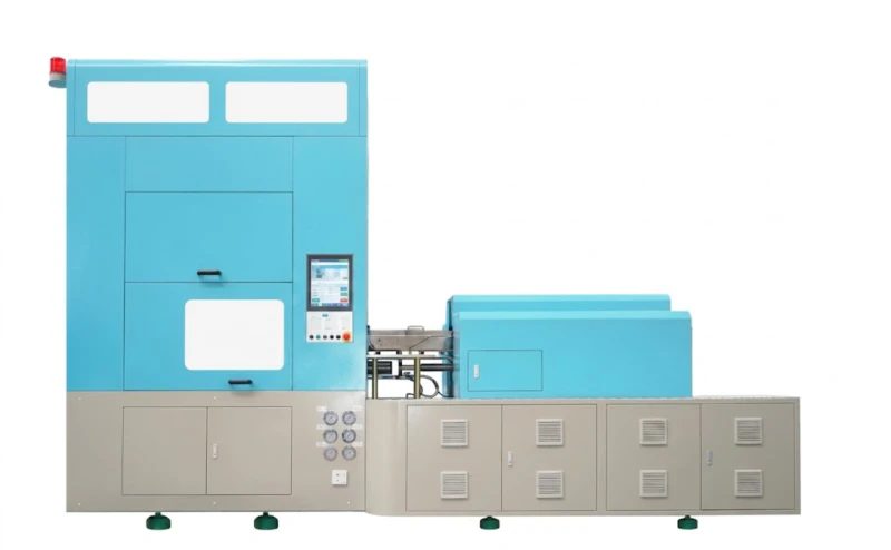
Fig. 2 — The HGY150-V4-EV injection station (right foreground) and rotary turntable. The injection platen locating ring, visible at the platen centre, automatically centres the preform mold during installation — eliminating the manual alignment step that accounts for 15–20 minutes of changeover time on machines without this feature.
7. Phase 5 — Process Parameter Transfer and First Article
Parameter setup is where the most time is lost on machines without a saved recipe system. An operator setting 40–60 individual parameters from memory — or from handwritten notes — introduces errors and takes 45–60 minutes. With a PLC recipe recall, the same operation takes under 5 minutes. Investing in a complete, verified parameter set for every product in the range is the highest-return changeover improvement available after pre-staging tooling.
7.1 Recipe Recall vs Manual Entry
| Parameter Group | No. of Values | Manual Entry Time | Recipe Recall Time |
|---|---|---|---|
| Barrel temperature zones | 5 – 7 | 5 min | Automatic |
| Injection pressure / speed profile | 8 – 12 | 10 min | Automatic |
| Holding pressure / time | 3 – 4 | 3 min | Automatic |
| Mold temperature setpoints | 3 – 6 | 5 min | Automatic |
| Blow pressure / timing profile | 6 – 10 | 8 min | Automatic |
| Cycle timing and turntable speed | 4 – 6 | 5 min | Automatic |
| Total parameter setup | 29 – 45 values | 36 – 50 min | Under 5 min |
7.2 First Article Verification
Run the machine at 60% cycle speed for the first 3–5 cycles after startup. Collect all bottles from the first full cycle and measure the following before approving production:
- ✓Gram weight per cavity — weigh one bottle from each cavity. Maximum acceptable deviation: ±1.5g or ±5% of target, whichever is smaller.
- ✓Neck thread dimensions — verify thread OD, neck height and sealing surface against the closure standard. Use a go/no-go gauge if available.
- ✓Bottle height and body diameter — measure at the specified reference points on the product drawing.
- ✓Visual inspection — check for weld lines, sink marks, haze, parting line flash and base clarity on all bottles from all cavities.
- ✓Closure fitment test — fit a production cap or pump to each bottle neck and verify correct engagement, no cross-threading and adequate sealing force.
8. ASB Mold Changeover: Special Considerations
For customers running Japanese Nissei ASB molds on our HGY150-V4 or HGY150-V4-EV machines, the changeover procedure follows the same phases described above, but with several specific additional steps that are unique to ASB tooling:
- →ASB neck ring retainer compatibility: ASB neck ring retainer plates use a different locating geometry than Henggang standard tooling. Verify before the first changeover that the correct ASB-compatible retainer plate is installed on the machine. This is a one-time check — once confirmed, it does not need to be repeated at subsequent changeovers with ASB tooling.
- →Hot runner nozzle tip compatibility: ASB preform molds use a specific nozzle tip geometry (gate diameter and taper angle). If switching between an ASB mold and a Henggang standard mold, verify that the hot runner nozzle tips are compatible before installation, or swap nozzle tips during the changeover. Mismatched tips cause gate quality defects and possible mold damage on the first injection shot.
- →Gram weight re-verification: Even when switching between two ASB molds of the same cavity count, re-verify gram weight at first article. Different preform designs — even for similar bottle volumes — can have different flow behaviour through the same hot runner system, resulting in fill imbalance that does not show up as a dimension problem but does show up as a weight variation between cavities.
- →Cooling water flow rate: ASB molds are engineered to specific cooling water flow rates. Our machines supply cooling water at 0.4–0.6 MPa — confirm this is adequate for each ASB mold before the first production run. If a mold’s cooling channels require a higher flow rate, a booster pump may be required at the mold inlet.
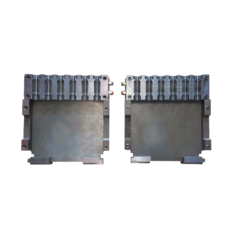
Fig. 3 — A complete ISBM tooling set: preform injection mold (left), blow mold halves (right) and neck ring assemblies (centre). Each set is specific to one bottle design. Organising tooling sets in dedicated labelled racks — with connection diagrams and parameter sheets stored alongside the mold — reduces changeover preparation time by 15–20 minutes per event.
9. Master Changeover Checklist
Print this checklist and complete it for every ISBM product changeover. Recording actual elapsed time at each phase allows progressive improvement across changeover events.
| Phase | Task | Target | Done |
|---|---|---|---|
| Prep (offline) | Retrieve and inspect incoming tooling | T-45 min | ☐ |
| Start pre-warming incoming molds | T-40 min | ☐ | |
| Retrieve / print PLC parameter recipe | T-30 min | ☐ | |
| Stage all tools and measuring instruments | T-20 min | ☐ | |
| Start drying new resin (if different grade) | T-4 hr | ☐ | |
| Shutdown | Close hopper gate — run down barrel | 5 min | ☐ |
| Purge barrel to clear extrudate | 5 min | ☐ | |
| Reduce barrel temp, isolate hot runner | 5 min | ☐ | |
| Disconnect water and air circuits | 5 min | ☐ | |
| Removal | Remove blow mold — inspect platen | 10 min | ☐ |
| Remove preform mold — inspect platen | 15 min | ☐ | |
| Remove neck rings and core rods — store correctly | 10 min | ☐ | |
| Install | Install and torque new core rods — check height | 10 min | ☐ |
| Install preform mold — connect hot runner and water | 15 min | ☐ | |
| Install neck rings — verify engagement | 5 min | ☐ | |
| Install blow mold — connect water | 10 min | ☐ | |
| Start-up | Recall PLC recipe — verify all parameters | 5 min | ☐ |
| Run 3 – 5 slow cycles, collect first article | 10 min | ☐ | |
| Measure gram weight, neck, height, visual — approve | 10 min | ☐ | |
| Total machine downtime (target) | 90 – 105 min | — | |
Post-changeover auxiliary check: After every mold changeover, verify that the compressed air supply pressure at the machine inlet is stable at the blow pressure setpoint before approving the first article. A new mold with different blow cavity volume may change the instantaneous air demand — if the oil-free air compressor for ISBM receiver tank pressure drops more than 0.3 MPa during the blow cycle, the compressor capacity is insufficient for the new product and receiver tank size should be increased before production resumes.
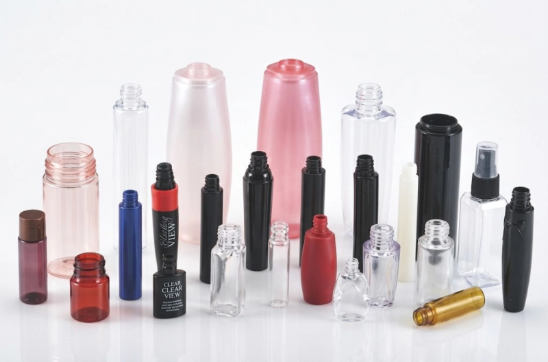
Fig. 4 — The measurable result of a well-executed ISBM changeover: on-specification PETG cosmetic bottles from the first approved production cycle. Achieving this within 90–105 minutes of machine shutdown requires every phase — preparation, tooling removal, installation, parameter recall and first article — to be executed to a documented standard.
1. Pre-stage offline. Every task done before the machine stops costs zero downtime. A 30-minute pre-stage routine consistently saves 45–60 minutes of machine downtime.
2. Use PLC recipe recall. Manual parameter entry is the single largest avoidable time loss. A complete, verified recipe library for every product in the range reduces parameter setup from 45 minutes to under 5.
3. Document and measure. Record actual elapsed time for each changeover phase. The act of measurement alone — without any other change — typically reduces changeover time by 15–20% as operators become aware of where time is being lost.
Need a Changeover Support Plan for Your ISBM Line?
Our engineers can review your current changeover procedure, identify the highest-impact improvements and build a product-specific parameter recipe library for your machine — reducing your changeover time and increasing productive hours per shift.