
Unplanned Downtime on an IBM Line Costs 10 to 20 Times More Than the Preventive Maintenance That Would Have Prevented It — Here Is the Complete Annual Programme That Keeps ZQ-Series Machines Running
An IBM machine that produces 20 million containers per year generates approximately USD 2,000 to 5,000 of production value per day at typical contract manufacturing rates. A 3-day unplanned downtime event — a hydraulic seal failure, a burned barrel heater, a damaged core pin, a seized rotary table bearing — costs USD 6,000 to 15,000 in lost production, plus the emergency repair cost, plus the risk of rush-order penalties to the customer. The annual preventive maintenance programme that prevents these events typically costs USD 3,000 to 6,000 in parts and 2 to 3 days of planned production interruption spread across the year. The return on preventive maintenance investment in IBM production is one of the highest in manufacturing.
This guide presents the complete 12-month preventive maintenance programme for ZQ-series IBM machines (ZQ40, ZQ60, ZQ60HE, and ZQ80), structured by maintenance interval: daily checks, weekly tasks, monthly tasks, quarterly tasks, semi-annual tasks, and annual overhaul items. Each maintenance item identifies what to check, what condition is normal versus requiring action, and what the consequence is of deferring the maintenance. The programme is designed to be implemented by production and maintenance teams without specialist IBM service engineer presence for routine tasks, while identifying the items that do require specialist involvement.
1. Preventive Maintenance Philosophy: Interval-Based vs Condition-Based
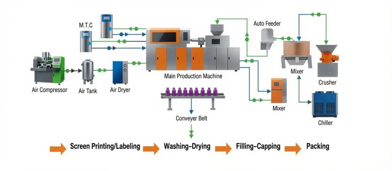
IBM machine maintenance follows two complementary approaches that together define the complete preventive maintenance programme:
Interval-Based Maintenance
Tasks performed at fixed time intervals regardless of apparent condition — daily, weekly, monthly, quarterly, semi-annual, and annual. Appropriate for components whose failure risk increases predictably with time or cycle count: hydraulic oil degradation, filter element loading, seal wear, bearing lubrication depletion, and screw wear. The interval is set at a conservative fraction of the expected service life to ensure the maintenance occurs before, not after, the component reaches its failure threshold.
Condition-Based Maintenance
Tasks triggered by measured condition — a component is inspected at fixed intervals and replaced or serviced when its measured condition reaches a defined threshold. Appropriate for components whose wear rate is variable and dependent on process conditions: core pin DLC coating wear (depends on resin abrasiveness and production speed), barrel and screw wear (depends on resin type and filler content), and mould cavity polish degradation (depends on resin and pigment). Regular measurement determines when service is needed rather than a fixed calendar date.
90%+
Target OEE on a well-maintained IBM pharmaceutical line with full PM programme in place
10:1
Typical ratio of unplanned downtime cost to the preventive maintenance cost that would have prevented it
2,000 h
Hydraulic oil change interval for ZQ40, ZQ60, and ZQ80 under normal production conditions
3 days
Typical total planned maintenance downtime per year if full PM programme is followed (versus 10 to 20 days unplanned if deferred)
2. Daily Maintenance Checks (Per Shift or Per Production Day)
Daily checks are operator-level observations that take 10 to 15 minutes at the start of each production shift. They detect emerging problems before they reach failure severity and provide the first line of machine condition monitoring. Each check should be recorded in the shift log with the observed condition.
| Check Item | Normal Condition | Action if Abnormal | Applies To |
|---|---|---|---|
| Hydraulic oil level | Sight glass reads between min and max marks at ambient temperature with machine off | Top up with the same oil grade to max mark; investigate source of loss (seal inspection at next weekly task) | ZQ40, ZQ60, ZQ80 |
| Hydraulic oil temperature | 35 to 55 degrees C during production; below 60 degrees C maximum | Above 60°C: check oil cooler water flow rate; check oil cooler for scale deposits; reduce production speed as interim measure | ZQ40, ZQ60, ZQ80 |
| Barrel temperature all zones | All zone actual temperatures within plus or minus 5 degrees C of setpoint after 30-minute warm-up | Zone not reaching setpoint: thermocouple or heater element fault — schedule replacement at next production break. Zone above setpoint: thermocouple fault or controller failure — stop production and investigate | All models |
| Cooling water supply/return temperature and flow | Supply temperature within 2 degrees C of chiller setpoint; return temperature less than 10 degrees C above supply; flow indicator showing positive flow on all circuits | High return temperature: reduced cooling — check for blocked circuit. No flow on a circuit: valve closed or hose kinked — restore flow before production starts | All models |
| Compressed air / blow air pressure | Supply pressure at machine blow air regulator within plus or minus 0.05 MPa of setpoint | Low pressure: compressor pressure or regulator fault. Pressure fluctuation: upstream supply issue or water in air lines — check air dryer and filter | All models |
| Hopper dryer temperature and dew point | Dryer air temperature at setpoint; supply air dew point below minus 40 degrees C (desiccant dryer) or within spec (hot air dryer) | Rising dew point on desiccant dryer: desiccant regeneration failure — service desiccant wheel; do not process resin until dew point returns to specification | All models |
| Visual inspection for leaks | No hydraulic oil on floor, machine base, or visible on hose surfaces; no water on floor from mould cooling connections | Oil drip: identify source and schedule seal replacement at next break. Water leak: check hose connection; tighten or replace fitting. Both: food-grade operations stop production for oil; pharmaceutical operations stop for any contamination | All models |
| IPC container weight (start of shift) | All cavity weights within IPC specification after production warm-up stabilisation (first 5 to 10 cycles) | Weight drift since previous shift: check barrel temperature stability, shot size setting. Specific cavity low or high: refer to troubleshooting framework | All models |
3. Weekly Maintenance Tasks
Weekly tasks are performed during a planned production stop — typically 1 to 2 hours at the end of the production week or during a shift changeover. They require access to specific machine systems and basic tools but do not require specialist IBM service engineers.
Hydraulic filter differential pressure check (ZQ40/ZQ60/ZQ80)
Check the hydraulic filter differential pressure indicator. Most ZQ-series hydraulic machines have a visual bypass indicator on the return line filter — a red button or indicator that pops when differential pressure across the filter exceeds approximately 3.5 bar, indicating the filter element is loaded. If the indicator is triggered, replace the filter element at the next available production stop. Do not reset the indicator without replacing the element. Filter bypass (indicated by the trigger) means particulate contamination is recirculating through the hydraulic system, accelerating wear on valves, cylinders, and the pump. Consequence of deferral: Accelerated valve wear, hydraulic seal abrasion, and potential pump damage from contaminated oil.
Nozzle and gate area inspection
Inspect the injection nozzle tip and the gate area of the injection cavity block for resin buildup, charred deposits, or wear. Resin that has overheated and carbonised at the nozzle tip will periodically dislodge and produce black speck contamination in containers. Clean any deposits from the nozzle tip and gate land using a brass wire brush (never steel — steel scratches the nozzle tip surface). Check the nozzle tip to injection sprue seat contact by confirming the nozzle seat area shows an even, circular contact ring — uneven contact indicates nozzle misalignment or a damaged seat requiring immediate attention. Consequence of deferral: Periodic black speck contamination events causing batch rejection.
Mould cooling circuit flow check
Verify flow indicator reading or rotameter reading for each cooling circuit during production. Compare to the baseline flow established at commissioning. Any circuit showing more than 10% reduction in flow rate from baseline indicates partial blockage — early-stage scale deposits in the channel that have not yet caused a detectable temperature rise. Address scale buildup proactively at the quarterly descaling service rather than waiting for the flow to deteriorate further. Record flow readings in the maintenance log for trend monitoring. Consequence of deferral: Progressive reduction in cooling effectiveness, increasing injection cooling dwell requirement, and eventual cycle time increase as cooling performance degrades.
Blow cavity vent inspection and cleaning
Inspect blow cavity vent slots under magnification (10x loupe or jeweller’s eyepiece). Vents that are partially blocked with resin residue or airborne contamination show as a dark discolouration within the vent slot. Clean any obstructed vents using compressed air directed along the vent slot, followed by a fine nylon bristle brush if residue remains. Do not use wire brushes or metal tools in vent slots — vent depth (0.015 to 0.04 mm) is easily altered by metal tool contact. Verify vent depth has not been inadvertently reduced below 0.01 mm by using a feeler gauge. Consequence of deferral: Surface haze, orange-peel texture, and localised matt patches on container body that increase reject rate and require troubleshooting time to diagnose.
Servo drive status check (ZQ60HE)
On the ZQ60HE all-electric machine, review the servo drive fault history log on the control HMI. Any recurring axis fault — even those that auto-reset without production interruption — should be investigated rather than ignored. A fault that occurs once may be a transient event; a fault that occurs three or more times in a week indicates a developing condition (encoder signal noise, drive temperature margin, power supply voltage variation) that will eventually cause a non-recoverable fault and production stop. Log all fault codes and occurrence times for the weekly maintenance record. Consequence of deferral: Developing servo faults escalate to non-recoverable production stops that require specialist servo drive service engineer attendance.
4. Monthly Maintenance Tasks
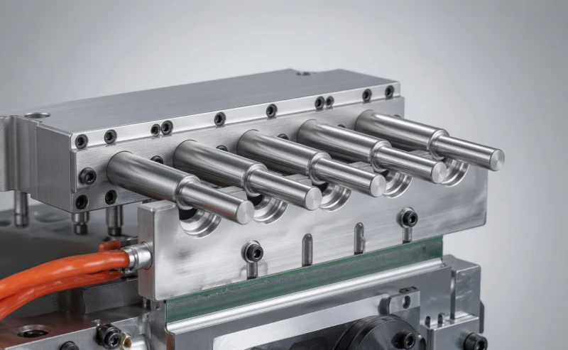
Core Pin DLC Coating Inspection
Inspect all core pins under 10x magnification for DLC coating condition. Well-maintained DLC surfaces appear uniformly dark and smooth with a slight sheen. Coating depletion shows as lighter, duller zones where the underlying H13 steel is exposed. Map any depleted zones by position on each core pin and measure against the reference inspection from commissioning. Schedule regrinding and recoating when depleted areas cover more than 10% of the critical surface zone (orifice bore and neck zone for pharmaceutical containers). Record inspection results with photographs for trend comparison at subsequent monthly inspections.
Consequence of deferral: increased stripping force, parison sticking, neck damage, and eventual out-of-specification I dimension from accumulated DLC depletion.
Injection Cavity Thread Surface Inspection
Inspect injection cavity thread surfaces under 10x magnification for polishing degradation and wear. A correctly maintained injection cavity thread surface should show a mirror-like polish (Ra 0.4 to 0.8 micrometres) with no visible scratches, pitting, or orange-peel texture. Thread flanks showing dull, scratched, or rough surfaces indicate that the cavity surface finish has degraded to the point where container neck thread quality is compromised. Schedule cavity polishing at this monthly inspection — do not wait until the neck thread dimensional specification is breached before restoring the surface.
Consequence of deferral: container neck thread surface roughness increasing, torque removal values drifting, closure fit degradation.
Rotary Table Position Repeatability Check
Attach a dial gauge to the machine frame with the probe contacting a reference point on the rotary table (a scribed line or a tooling reference pin). Run 20 automatic table index cycles and record the table stop position at each cycle. The variation in stop position across 20 cycles should be within plus or minus 0.05 mm. Variation above plus or minus 0.1 mm indicates table drive bearing wear or table drive servo/hydraulic positioning error that is beginning to affect core pin alignment at the injection and blow stations. Investigate and address before the variation reaches plus or minus 0.2 mm, at which point cavity misalignment produces detectable container dimensional variation.
Consequence of deferral: progressive core pin misalignment, parison eccentricity, and eventual core pin contact damage to injection cavity or blow cavity.
Barrel Zone Temperature Calibration Verification
Verify barrel zone temperature accuracy by measuring actual melt temperature with a calibrated pyrometer at the nozzle and comparing to the zone setpoints. The melt temperature at the nozzle should be within plus or minus 5 degrees C of the expected melt temperature for the programmed barrel zone profile. A significant discrepancy (more than 10 degrees C) indicates thermocouple drift or heater element degradation affecting one or more barrel zones. Replace thermocouples showing drift above 5 degrees C from calibrated reference; schedule heater element replacement for zones unable to reach setpoint.
Consequence of deferral: process running at incorrect melt temperature, affecting injection fill, container dimensions, and for PET: increased acetaldehyde generation from elevated temperature.
5. Quarterly Maintenance Tasks
Quarterly tasks require a planned 4 to 8-hour maintenance window and involve partial disassembly of machine and tooling systems. They represent the most time-intensive routine maintenance events and should be scheduled at the quarterly production planning stage to minimise schedule impact.
Hydraulic Filter Element Replacement (ZQ40/ZQ60/ZQ80)
Replace the hydraulic return line filter element and the suction filter element regardless of whether the bypass indicator has been triggered. Even without bypass indication, filter elements accumulate fine particulate below the bypass threshold that reduces flow capacity and harbours biological contamination (in water-containing oil systems). Use only the filter element specification from the machine manual — generic elements of similar size may not meet the filtration rating (typically 10 micrometre absolute) required for ZQ-series hydraulic systems. Record the element condition at removal (colour, odour of any contamination) as an indicator of system health.
Cooling Circuit Descaling
Circulate a descaling solution (2 to 3% citric acid or proprietary non-corrosive descaler, compatible with the mould steel and copper fittings) through all injection cavity and blow cavity cooling circuits. Circulate for 30 to 60 minutes at low flow rate. Flush with clean water for 15 minutes after descaling. Measure flow rate after descaling and compare to pre-descaling flow — an improvement of more than 5% confirms scale was present. After descaling, recheck all flow rates against the commissioning baseline and confirm they are within 10% of baseline values. For facilities with very hard water (above 300 ppm hardness), increase descaling frequency to monthly.
Hydraulic Cylinder Rod Seal Inspection (ZQ40/ZQ60/ZQ80)
Inspect all hydraulic cylinder rod seals by wiping each rod with a clean white cloth after running the axis through its full stroke. Oil on the cloth indicates rod seal seepage — classify as trace (oil film — monitor), weeping (oil streak — plan replacement at next quarterly), or active leak (continuous oil drip — replace immediately). For pharmaceutical and food-contact IBM production, any hydraulic seal seepage requires immediate action to prevent oil contamination risk — replace seals rather than monitoring at trace level as would be acceptable in a non-food application. Record seal condition per cylinder in the maintenance log.
Ball Screw Lubrication (ZQ60HE)
Apply the specified grease (typically a lithium complex base grease, NLGI Grade 2, specified in the ZQ60HE maintenance manual) to the lubrication fittings on each ball screw assembly — injection advance, clamping mechanism, and stripping drive. Apply until fresh grease appears at the ball nut outlet. Wipe excess grease from the exposed screw sections to prevent accumulation of dust and resin particles that would act as abrasives in the screw nut interface. Record the lubrication date, grease type and quantity per fitting in the maintenance log. Inadequate ball screw lubrication is the primary cause of premature ball nut wear on all-electric machines.
Desiccant Dryer Regeneration System Check
Verify the desiccant regeneration heater is achieving its setpoint temperature (typically 160 to 200 degrees C during the regeneration cycle). Measure supply air dew point at the dryer outlet with a calibrated dew point meter and confirm it is below minus 40 degrees C. If dew point has risen above minus 30 degrees C, the desiccant is losing effectiveness — inspect the desiccant bed for contamination (resin fines, oil mist from contaminated compressed air) and replace the desiccant if contaminated. A desiccant dryer that cannot achieve minus 40 degrees C dew point is not fit for PET drying and the root cause must be identified before PET production resumes.
6. Semi-Annual Maintenance Tasks

| Task | Procedure | Action Threshold | Applies To |
|---|---|---|---|
| Screw and barrel wear measurement | Withdraw screw from barrel; measure screw flight OD at 5 positions along screw length using an outside micrometer. Measure barrel bore ID at 3 positions using an internal gauge. Calculate the clearance between screw flight OD and barrel bore ID. | Clearance above 0.15 mm: plan replacement within 6 months. Clearance above 0.25 mm: replace at next scheduled maintenance window (continued operation risks intermixing and shot weight variation) | All models |
| Check valve ring inspection | Remove screw and inspect check valve ring (non-return valve) for wear, damage, or incomplete seating. Check valve condition is critical for shot weight repeatability: a worn check valve allows melt to flow back during injection, reducing the effective shot weight and producing inconsistent container weights. | Visible wear ring on seating face, ring not seating flat, or ring movement greater than 0.5 mm: replace check valve assembly. Check valve replacement is a consumable item costing USD 150 to 400 — replace proactively at semi-annual service rather than waiting for shot weight variation to diagnose it | All models |
| Rotary table bearing lubrication | Apply specified bearing grease to the rotary table thrust bearing and radial bearing lubrication fittings according to the machine maintenance manual specification. Rotate the table by hand after lubrication to distribute grease evenly. | Any grittiness or rough feeling when rotating the table by hand indicates bearing contamination or wear — investigate with bearing specialist before continuing high-cycle production | All models |
| Hydraulic oil sampling and analysis | Draw a 100 ml oil sample from the hydraulic reservoir mid-level port (not the drain — drain samples are unrepresentative due to settled sediment). Send to an oil analysis laboratory for viscosity, water content, acid number, wear metal concentration, and particle count. | Water above 0.05%: investigate water ingress (cooler leak). Acid number above 2.0 mg KOH/g: oil degradation — change oil immediately. Iron above 50 ppm: pump or cylinder wear. Particle count ISO 4406 above 17/15/12: change oil and investigate contamination source | ZQ40, ZQ60, ZQ80 |
| Servo encoder cable and connector inspection (ZQ60HE) | Visually inspect all servo motor encoder cables for chafing, kinking, or connector corrosion at each axis. Encoder cable damage is the most common cause of intermittent servo faults on all-electric IBM machines. Pay particular attention to cables at the injection advance axis where thermal cycling from barrel heat causes repeated cable flexing. | Any cable showing outer jacket damage, tight bending radius below 50 mm, or corroded connector pins: replace before the cable fails in production. An encoder cable replacement costs USD 80 to 200; an unplanned production stop from encoder failure typically costs USD 2,000 to 5,000 in lost production plus emergency service call | ZQ60HE |
7. Annual Overhaul: The Full Machine Service
The annual overhaul is the most comprehensive planned maintenance event and typically requires 2 to 3 production days. It combines all semi-annual and quarterly tasks with additional deep-service items that are not accessible or practical on shorter maintenance windows. For pharmaceutical IBM lines, the annual overhaul is also the point at which the process validation periodic review is conducted and any re-qualification requirements are identified.
Hydraulic Oil Change
Drain the complete hydraulic reservoir (150 to 400 litres depending on model), flush the reservoir with a small quantity of fresh oil, clean the reservoir interior visually for sludge or corrosion, replace the drain plug seal, and refill with fresh oil of the specified grade (typically ISO VG 46 or VG 68 hydraulic oil meeting HM/HV specification). Record the oil brand, grade, and quantity in the maintenance log. Keep a sample of the drained oil for archival comparison — a significant change in oil colour or condition relative to the previous year’s sample warrants oil analysis even if semi-annual sampling showed normal results.
Cost: USD 400 to 800 in oil and labour. Consequence of deferral: oil viscosity index degradation, valve response variation, pump wear from degraded lubrication film.
Injection Unit Disassembly and Inspection
Withdraw and fully inspect the screw, check valve assembly, and barrel bore. Clean the barrel interior with a purge compound and lint-free wipes. Measure screw flight OD and barrel bore ID at multiple positions. Inspect screw flight surfaces for chipping, erosion, or plating wear. Inspect barrel bore surface for corrosion, pitting, or scoring. Replace check valve assembly as standard annual consumable. Replace screw and barrel when wear measurements reach action threshold from semi-annual measurement trend.
Cost: USD 200 to 400 in labour plus parts. Consequence of deferral: progressive shot weight inconsistency, molecular weight degradation pockets from dead zones in worn barrel.
Instrument Calibration
Calibrate all machine instruments against traceable standards: barrel thermocouple calibration (compare to calibrated reference thermocouple at four temperature setpoints); injection pressure transducer calibration (compare to calibrated pressure gauge at three setpoints); position sensor verification (for servo axes: compare encoder-reported position to physical measurement); cooling water temperature sensor calibration. For pharmaceutical IBM, this calibration is a GMP requirement and must be documented with calibration certificates referencing the traceable calibration standards used.
Consequence of deferral: validated process parameters may be applied at incorrect actual conditions, creating undocumented process deviation risk.
Electrical Panel and Cable Inspection
Open the main electrical panel and visually inspect all terminal connections for corrosion, discolouration (heat damage), or loose terminals. Check all cable gland seals for integrity. Inspect all panel cooling fan operation. For ZQ60HE: inspect servo drive cooling fans and heat sink fins for dust accumulation — clogged servo drive cooling reduces thermal margin and accelerates drive component aging. Clean fans and heat sinks with dry compressed air if dust accumulation is present.
Consequence of deferral: loose connections cause intermittent electrical faults; servo drive overheating accelerates capacitor and IGBT degradation.
Safety System Full Test
Test all safety systems with full documented records: E-stop function on each E-stop button; safety gate interlock with machine motion verified to stop within specification response time; light curtain function test; low hydraulic pressure shutdown (verify by temporarily restricting supply); over-temperature shutdown on barrel zones (verify by advancing setpoint above safety limit). For pharmaceutical GMP facilities, this annual safety test is typically a regulatory requirement documented in the site safety management system.
Consequence of deferral: safety system faults that do not trigger automatically may allow machine operation in unsafe condition.
8. Mould Tooling Maintenance Programme
Mould tooling has its own maintenance programme that runs in parallel with the machine programme. Tooling maintenance is condition-based — it is triggered by measured dimensional drift or surface quality degradation rather than fixed time intervals, since wear rate depends heavily on production volume, resin abrasiveness, and cavity count.
| Tooling Component | Inspection Interval | What to Measure | Service Trigger | Service Action |
|---|---|---|---|---|
| Core pins (all) | Every 1 to 2 million cycles | Orifice bore diameter (for dropper containers); neck bore diameter; DLC coating condition (visual under 10x) | Dimension drift consuming more than 50% of total tolerance; DLC depleted on more than 10% of critical surface | Regrind to nominal diameter; DLC recoating; replace if below minimum diameter after regrind |
| Injection cavity (neck zone) | Every 3 to 5 million cycles | Thread T, E dimensions; cavity surface finish Ra (profilometer); parting line flatness | Dimension drift consuming more than 50% of tolerance; Ra above 0.8 micrometres; parting line step above 0.02 mm | Polish cavity to Ra 0.4 to 0.6 micrometres; regrind thread if dimension drift; regrind and re-lap parting line |
| Blow cavity (body zone) | Every 5 to 8 million cycles | Body diameter at maximum diameter; cavity surface finish; vent depth (feeler gauge); parting line condition | Diameter outside tolerance; Ra above 0.6 micrometres; vent depth below 0.01 mm; parting line step above 0.02 mm | Polish cavity body; restore vent depth by re-machining; regrind parting line; replace cavity insert if below minimum wall |
| Stripping plate | Every 3 to 5 million cycles | Neck contact face condition; contact bore diameter (should match container neck E dimension within plus or minus 0.05 mm) | Visible burring or galling on neck contact face; contact bore diameter outside plus or minus 0.1 mm of specification | Regrind and re-lap contact face; bore re-machine to nominal dimension |
| Runner system | Every 5 million cycles | Runner branch cross-sections (compare to commissioning baseline); runner surface polish; gate land condition | Inter-cavity weight variation above 3% despite process optimisation; gate land showing erosion or carbonised deposit buildup | Clean runner channels; repolish; adjust branch cross-sections if weight imbalance persists; re-machine gate land if eroded |
9. Hydraulic vs All-Electric: How the Maintenance Programme Differs

| Maintenance Category | Hydraulic IBM (ZQ40/ZQ60/ZQ80) | All-Electric IBM (ZQ60HE) | Difference |
|---|---|---|---|
| Drive oil system | 200 to 400 L annual oil change; quarterly filter; semi-annual sampling; daily level and temperature check | Not applicable — zero hydraulic oil | All-electric eliminates the single largest maintenance cost and time burden of hydraulic IBM; annual saving of USD 800 to 1,500 in oil and filter cost alone |
| Drive seals | Quarterly inspection of 5 to 8 cylinder rod seals; annual full seal kit replacement | Ball screw seals only — quarterly inspection; 2 to 3-year replacement interval | Substantially lower seal maintenance burden; no oil contamination risk from seal failure |
| Drive lubrication | Hydraulic oil provides lubrication — covered by oil system maintenance | Ball screw grease every 3 months; guide rail lubrication every 6 months | All-electric requires proactive lubrication management of ball screws — more visible task but lower total volume of lubricant |
| Control system | PLC and HMI standard maintenance; proportional valve calibration annually | Servo drive status weekly; encoder cable semi-annual; servo drive calibration annual | All-electric requires more sophisticated electrical maintenance competence but lower mechanical maintenance burden |
| Total drive maintenance cost (annual estimate) | USD 1,400 to 2,500 per machine | USD 600 to 1,000 per machine | All-electric drive maintenance cost is 40 to 60% lower than hydraulic; over 10 years represents USD 8,000 to 15,000 additional savings per machine beyond energy cost difference |
10. Maintenance Records and KPI Tracking
A preventive maintenance programme without systematic record-keeping is little better than reactive maintenance — the records are what allow trend analysis, provide evidence of programme compliance for audits, and enable the calculation of maintenance effectiveness KPIs. The following records are the minimum requirement for a GMP-compliant IBM maintenance programme:
Shift Log
Daily records of: shift production hours, containers produced, IPC results (weights and dimensions), any alarms or faults with resolution, operator name. Retained for minimum 2 years (5 years for pharmaceutical). Forms the basis of OEE availability calculation.
Planned Maintenance Record
For each maintenance event: date, machine ID, tasks completed, parts replaced (with part numbers and quantities), technician name, observations. Signed and dated. For pharmaceutical: quality review signature required before return to production for any maintenance involving product contact surfaces.
Tooling Dimensional Record
Measurement results from each core pin and cavity inspection: dimension values, cumulative cycle count at measurement, comparison to commissioning baseline, and action taken (no action, scheduled service, immediate service). Graphed as a trend over time to predict remaining tooling service life.
Calibration Record
Annual calibration results for all instruments: thermocouple calibration certificates, pressure transducer calibration certificates, servo position verification data. Each certificate must reference the traceable calibration standard used and be retained for the lifetime of the instrument plus 5 years.
Key Maintenance KPIs
| KPI | Calculation | World-Class Target |
|---|---|---|
| MTBF (Mean Time Between Failures) | Total production hours / number of unplanned stoppages above 15 minutes | Above 500 hours |
| MTTR (Mean Time to Repair) | Total unplanned downtime hours / number of repair events | Below 2 hours |
| PM Compliance Rate | PM tasks completed on schedule / PM tasks due x 100% | Above 95% |
| Machine Availability | (Scheduled hours – unplanned downtime) / Scheduled hours x 100% | Above 92% |
| Planned vs Unplanned Maintenance Ratio | Planned maintenance hours / Total maintenance hours x 100% | Above 80% |
11. Frequently Asked Questions
Q: Our IBM machine has been running for 3 years with no major maintenance. Where should we start a catch-up maintenance programme?
Start with a condition assessment to determine which systems are most degraded — do not simply apply the full quarterly and annual programme simultaneously, as some items may be overdue to the point where the service action reveals additional damage requiring planning. Recommended catch-up sequence: (1) Immediately: hydraulic oil sampling and analysis — this gives the fastest insight into the state of the hydraulic system (if iron and acid number are severely elevated, the pump and valves may already be damaged); (2) This week: hydraulic filter replacement, nozzle inspection, IPC weight and dimension check per cavity to identify any tooling drift; (3) This month: hydraulic oil change, core pin DLC inspection, cooling circuit descaling, rotary table repeatability measurement; (4) Next quarter: full quarterly plus semi-annual programme, including screw and barrel measurement, seal inspection, and calibration verification. After catch-up, implement the standard programme going forward and document all findings from the catch-up assessment as the new condition baseline.
Q: How do we calculate the cumulative cycle count for tooling maintenance triggers when the machine counter was reset during a repair?
If the machine cycle counter has been reset and the cumulative cycle count is unknown, reconstruct it from production records. Calculate: average cycle time (from process records) x total production hours (from shift logs) = estimated total cycles. If shift logs are not available, use the container output records: total containers produced / number of cavities = cycles. Where production records are also unavailable, treat the tooling as unknown-history and perform a full dimensional measurement and DLC coating inspection to determine current condition. Based on the measured condition, estimate remaining life from the typical wear rates for your resin and production speed. Going forward, implement a cumulative cycle count log that is maintained separately from the machine counter and cannot be reset during machine maintenance.
Q: Can we extend the hydraulic oil change interval from 2,000 hours to 3,000 hours based on oil analysis results?
Yes — oil analysis results can support an extended drain interval if the analysis consistently shows all parameters within acceptable limits at the 2,000-hour point. The protocol for an extended drain interval: conduct oil analysis at 2,000 hours as usual. If viscosity is within plus or minus 10% of new oil viscosity, acid number is below 1.0 mg KOH/g, water content is below 0.02%, and wear metal concentrations are below alert levels, continue operation and repeat sampling at 2,500 hours. If the 2,500-hour sample also passes all criteria, change the oil at 3,000 hours and establish 3,000 hours as the new interval — with the requirement that semi-annual sampling at the 1,500-hour mid-point is added to catch any accelerated degradation. Do not extend the drain interval without the mid-point sample to provide early warning of unexpected degradation. The 2,000-hour interval is a conservative default based on typical operating conditions; extension based on actual condition data is entirely appropriate and reduces oil consumption and disposal cost.
Q: What spare parts should be held in inventory to support the 12-month maintenance programme without long procurement lead times?
The recommended spare parts inventory for a ZQ-series IBM machine supporting the 12-month PM programme: (1) Consumables replaced at known intervals — hold 12-month supply: hydraulic filter elements (4 for quarterly replacement), barrel heater elements (1 set per zone), thermocouples (1 per zone), check valve assembly (1), nozzle tip (1); (2) Condition-based replacements — hold 1 unit: hydraulic seal kit for each cylinder type; ball screw grease (1 kg for ZQ60HE); encoder cables for each axis type (ZQ60HE); (3) Core tooling spares — hold based on production risk: 1 complete core pin set per cavity size if core pin failure would stop production; 1 blow cavity vent repair kit; (4) Emergency spares — hold based on lead time: one servo drive unit per axis type for ZQ60HE (if delivery lead time exceeds 2 weeks); one hydraulic proportional valve for ZQ40/ZQ60/ZQ80 (if lead time exceeds 1 week). Review and update the spare parts inventory annually, removing unused items and adding newly identified critical parts based on the year’s maintenance experience.
12. Conclusion: The 12-Month Maintenance Calendar
Preventive maintenance on IBM machines is not a cost — it is an investment with a measured, calculable return. The 12-month programme described in this guide requires approximately 2 to 3 days of planned downtime spread across the year and USD 3,000 to 6,000 in parts for a ZQ60 or ZQ60HE production line. It prevents the unplanned failures that consume 10 to 20 days of unplanned downtime per year on lines without a structured PM programme, with repair and lost production costs of USD 30,000 to 80,000.
12-Month Maintenance Calendar — Summary
| Interval | Downtime Required | Key Tasks | Performed By |
|---|---|---|---|
| Daily | 15 min per shift | Oil level, barrel temperatures, cooling water flow, leak check, IPC at shift start | Operator |
| Weekly | 1 to 2 hours | Hydraulic filter check, nozzle inspection, blow vent cleaning, cooling flow check, servo fault log review | Operator / Maintenance |
| Monthly | 2 to 4 hours | Core pin DLC inspection, cavity thread inspection, table repeatability check, barrel thermocouple verification | Maintenance / Process Engineer |
| Quarterly | 4 to 8 hours | Hydraulic filter replacement, cooling circuit descaling, hydraulic cylinder seal inspection, ball screw lubrication (ZQ60HE), desiccant dryer check | Maintenance |
| Semi-Annual | 8 to 16 hours | Screw and barrel wear measurement, check valve replacement, table bearing lubrication, hydraulic oil sampling, encoder cable inspection (ZQ60HE) | Maintenance / Specialist |
| Annual | 2 to 3 days | Hydraulic oil change, full injection unit service, instrument calibration, electrical panel inspection, safety system full test, tooling dimensional measurement and service | Maintenance + Specialist |
Our service engineering team provides annual IBM machine service contracts for ZQ-series machines, covering the annual overhaul, instrument calibration with traceable calibration certificates, tooling dimensional inspection, and priority response for unplanned failures. Contact us with your machine model and installation date to discuss a service contract for your production line.
IBM Machine Service and Maintenance Support
Our service engineering team provides annual overhaul service, instrument calibration, tooling inspection and refurbishment, spare parts supply, and priority unplanned failure support for ZQ40, ZQ60, ZQ60HE, and ZQ80 IBM machines. Contact us to discuss a maintenance service contract for your production line.